In testing since 8 Oct 2026. Features may change or be added while we test. What you enter is kept: nothing will be lost. Tell us what goes wrong.
Support

Builders Log

Rans S-21 Summit TT

RANS S-21 Outbound · Built by William VonDane · CO15 · Started 2 Apr 2026 · 31 entries

Sections

  • Shop preparation90%
  • Delivery or pickup90%
  • Empennage90%
  • Wings80%
  • Fuselage40%
  • Landing gear10%
  • Powerplant10%
  • Electrical and avionics20%
  • Interior
  • Paint and finish
  • Final assembly

11 Oct 2026

Electrical and avionics

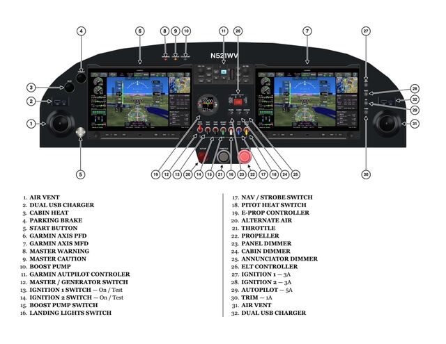
Created Instrument panel equipment description for POH

  • Instrument panel equipment description

    Instrument panel equipment description

30 Jun 2026

Wings

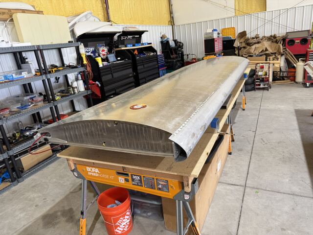
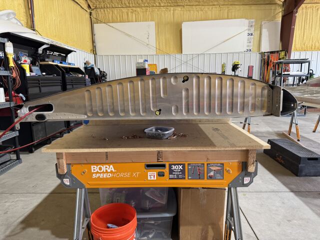
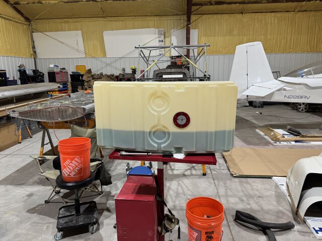
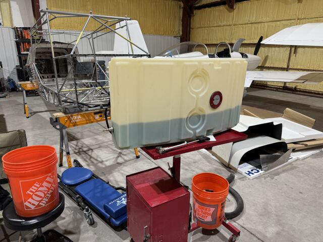
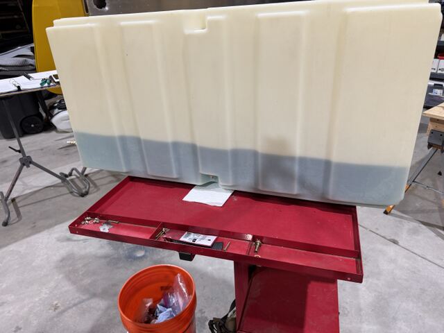
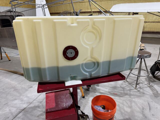
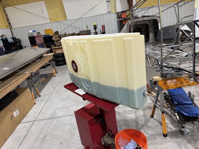
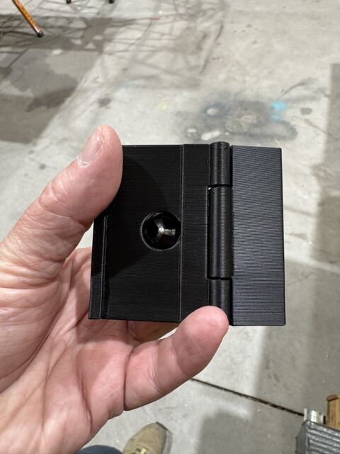
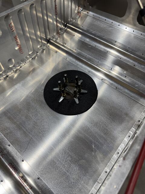
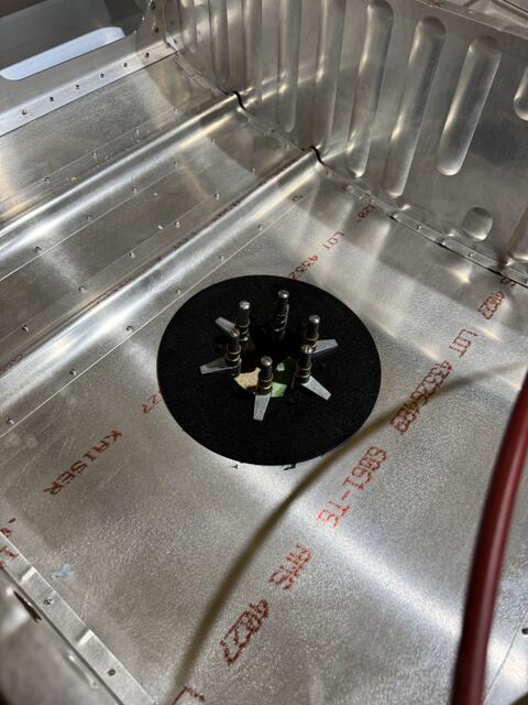
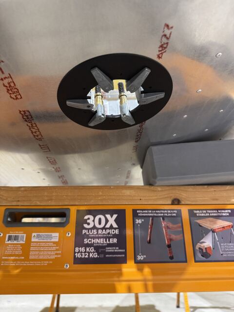
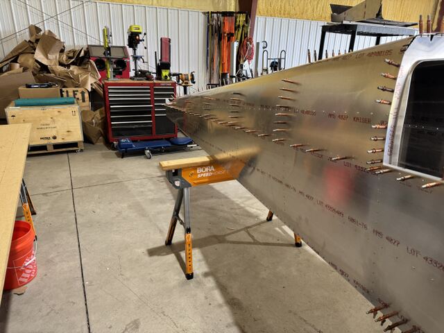
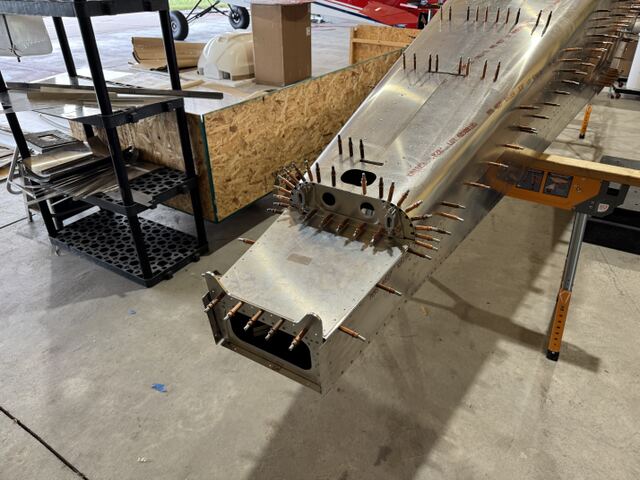
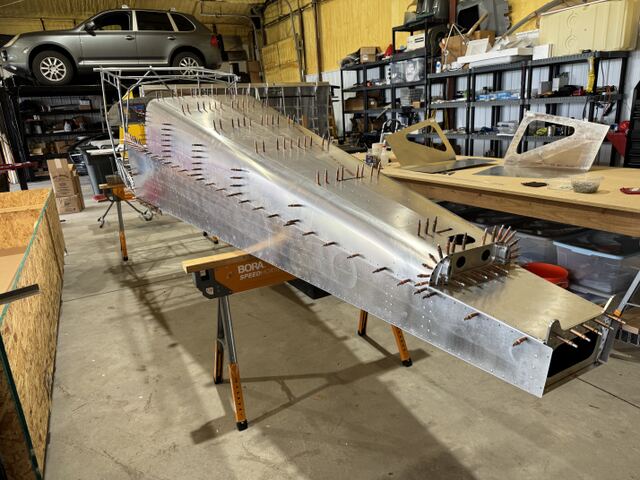
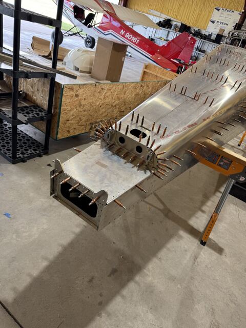
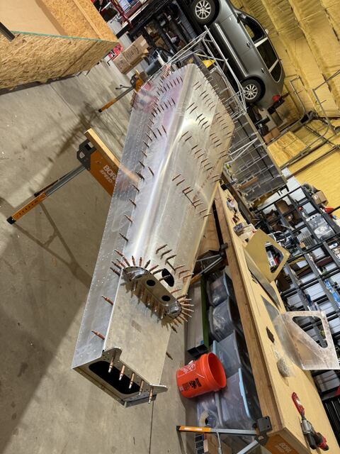
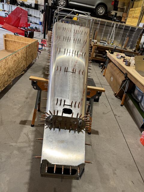
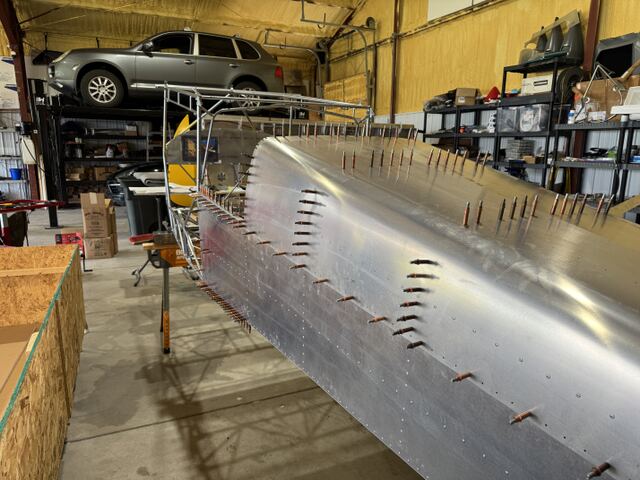
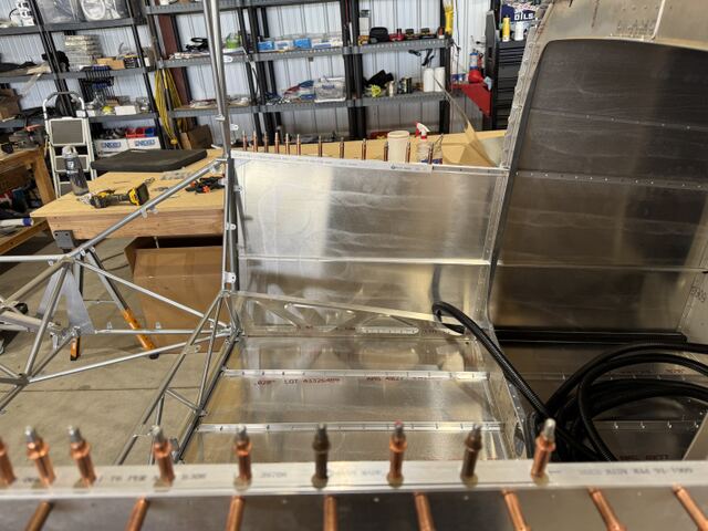
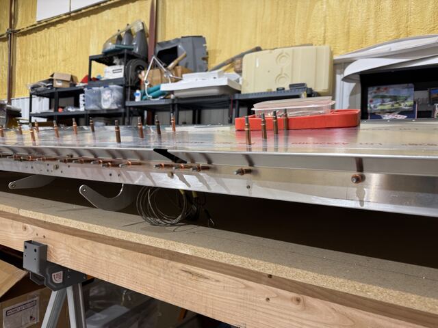
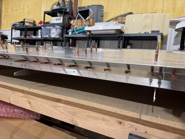
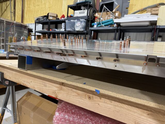
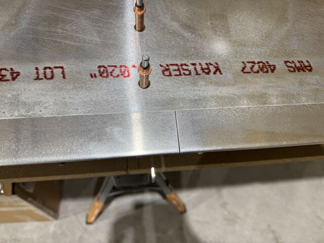
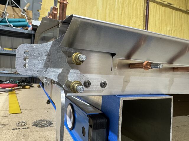
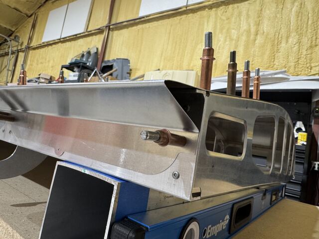
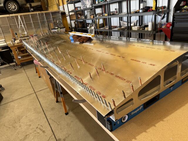
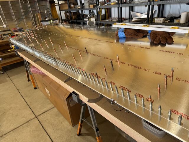
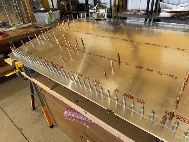
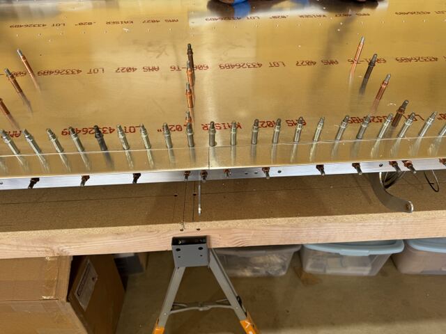
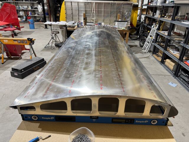
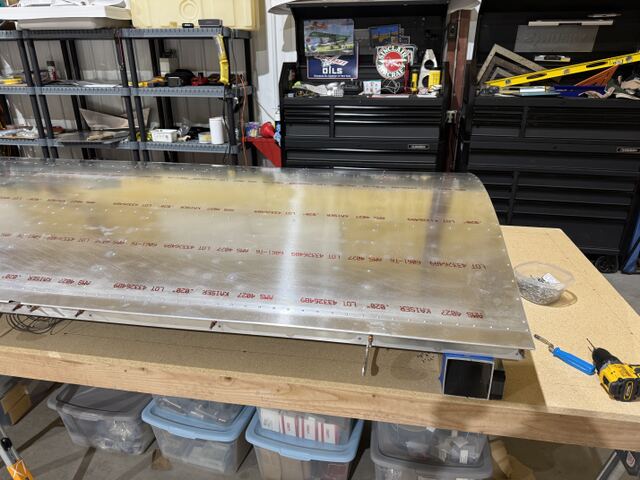
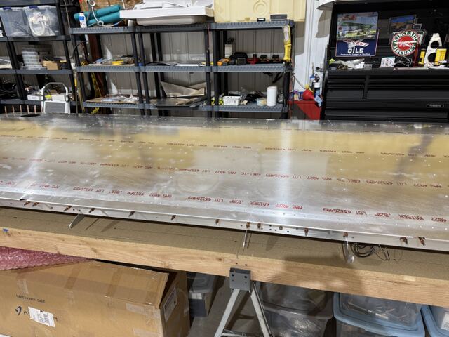
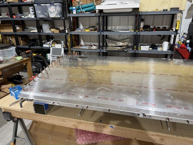
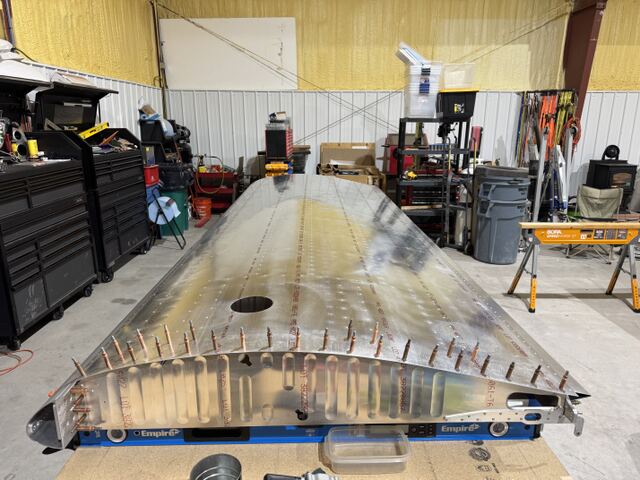
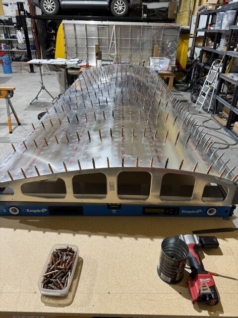
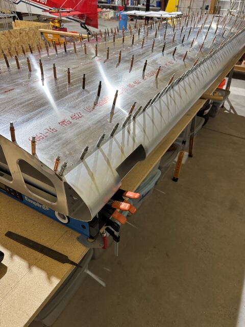
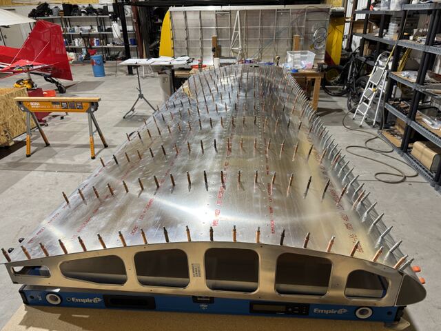
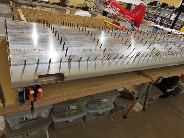
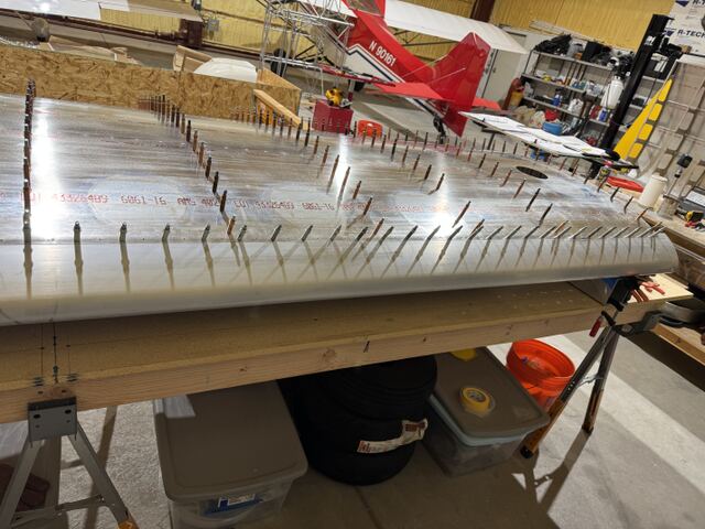
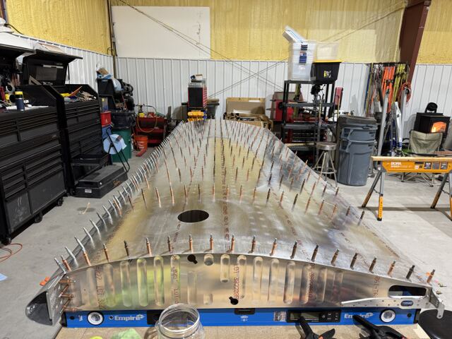
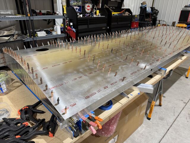
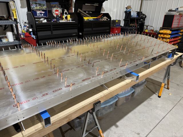
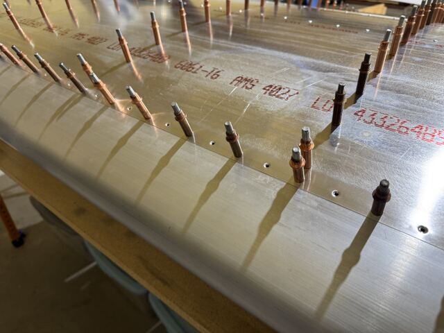
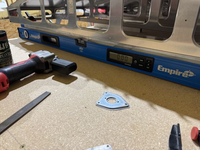
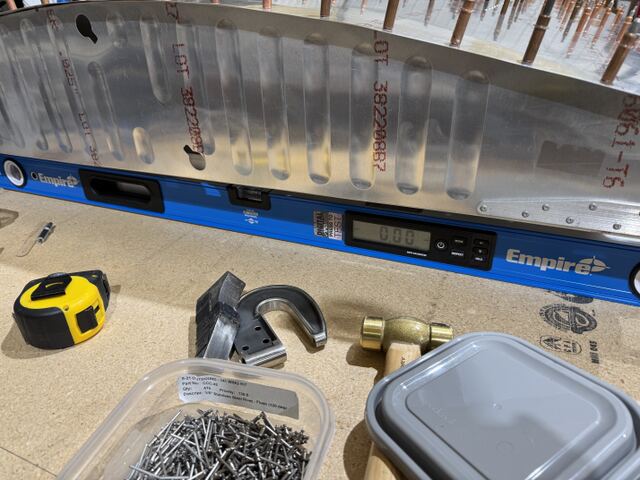
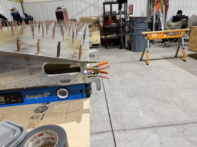
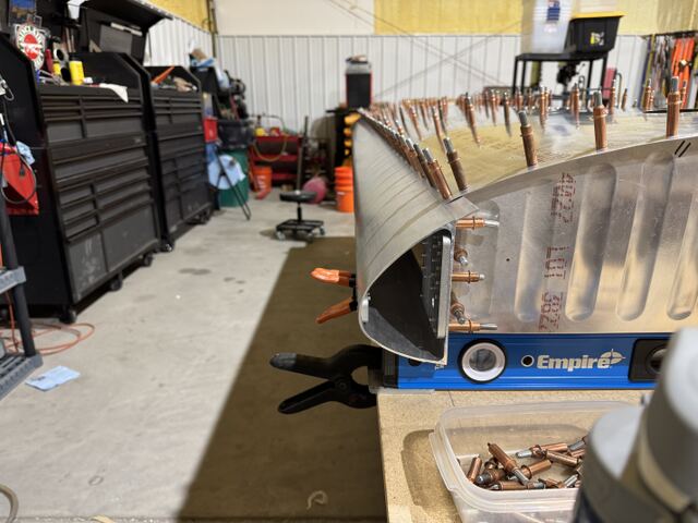
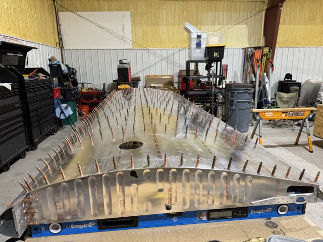
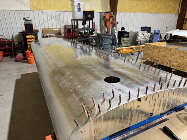
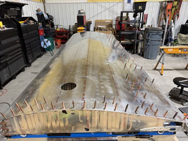
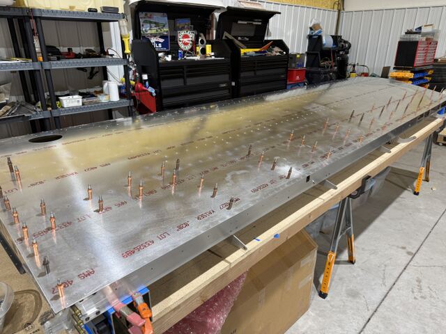
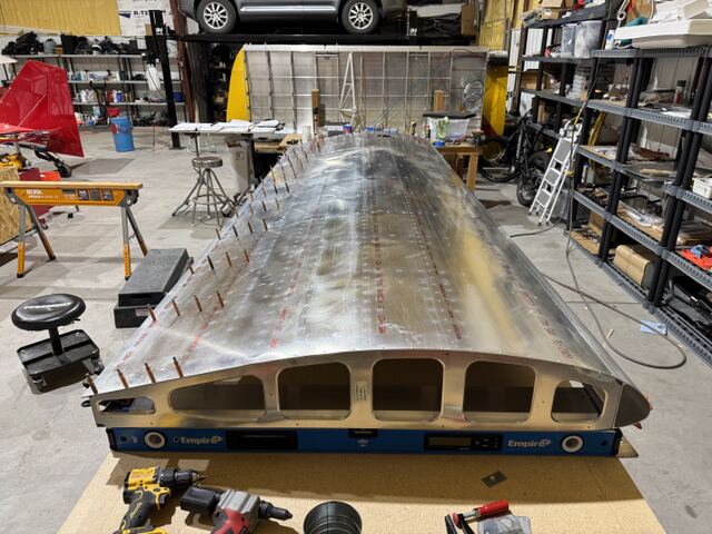
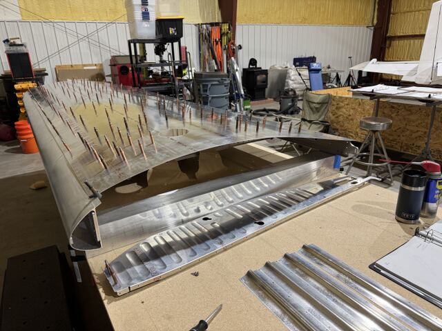
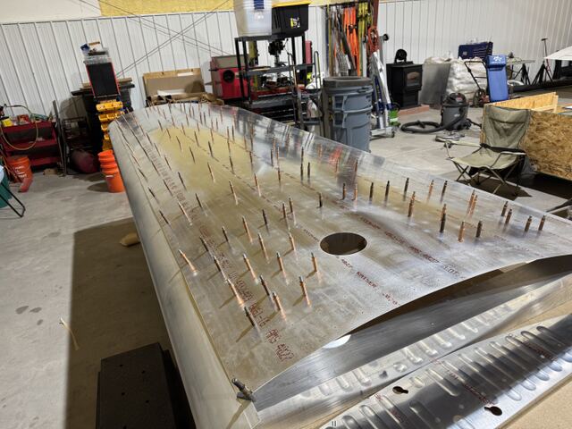
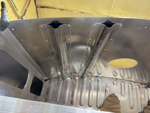
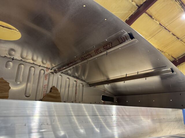
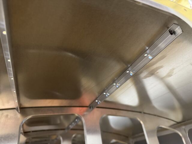
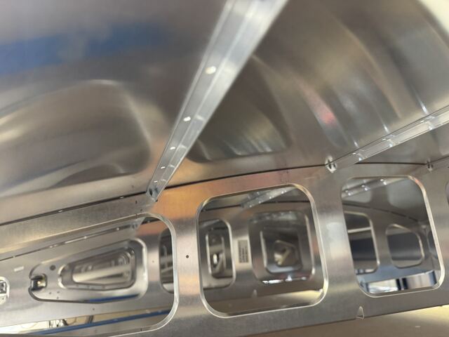
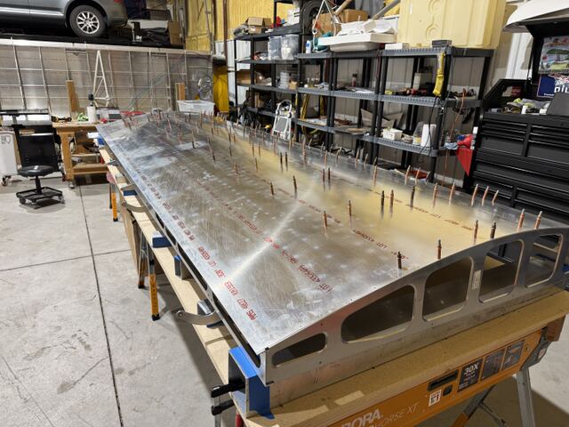
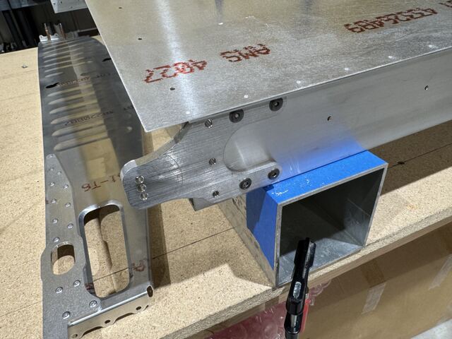
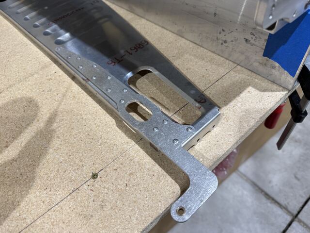
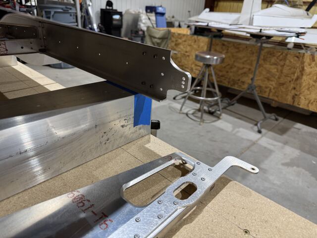
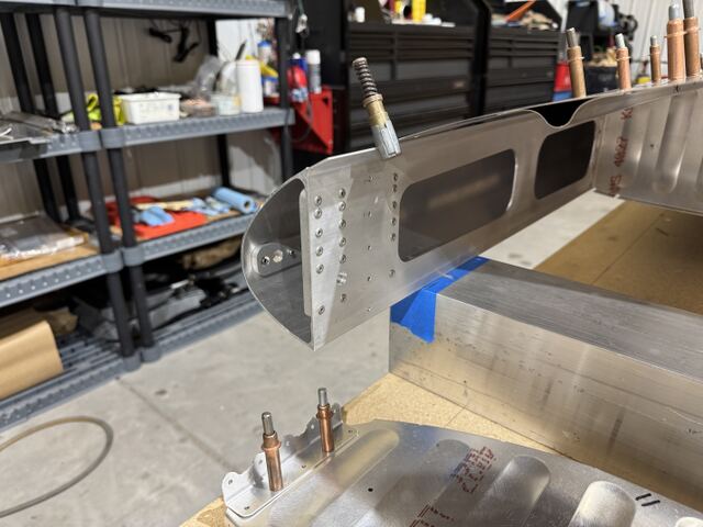
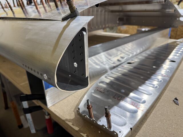
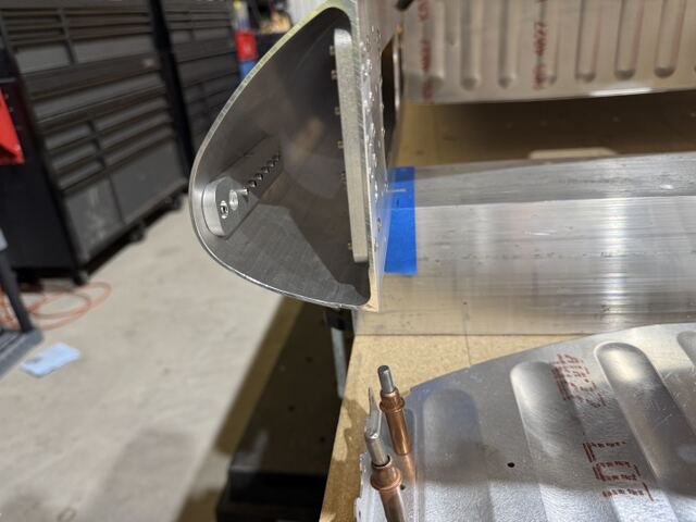
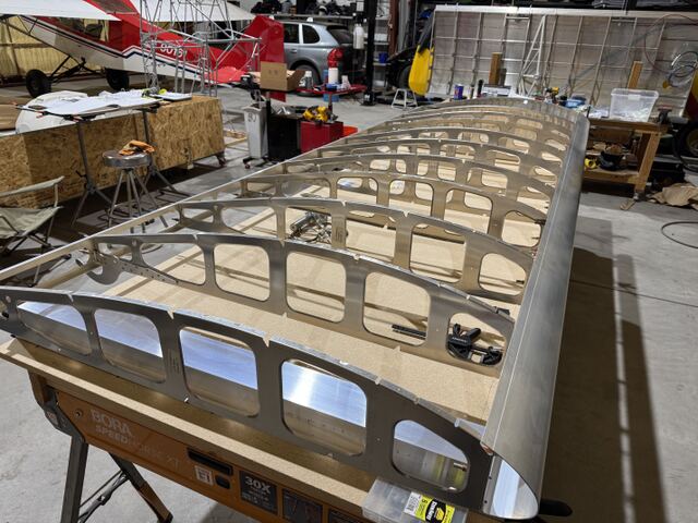
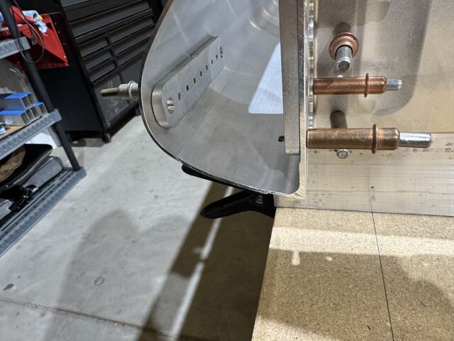
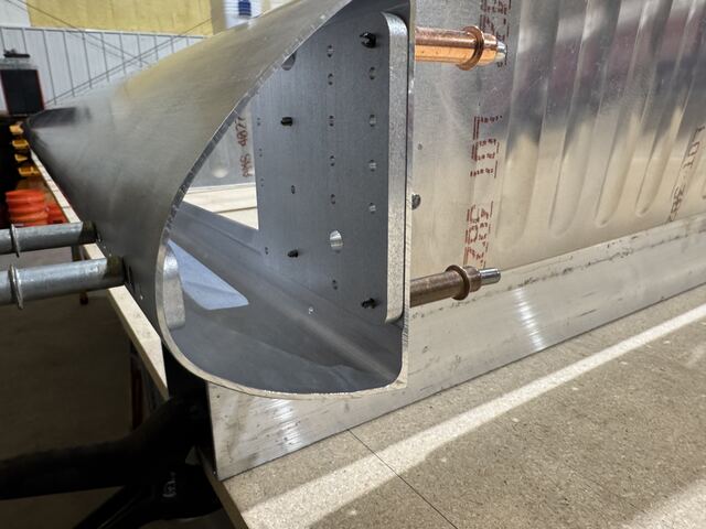
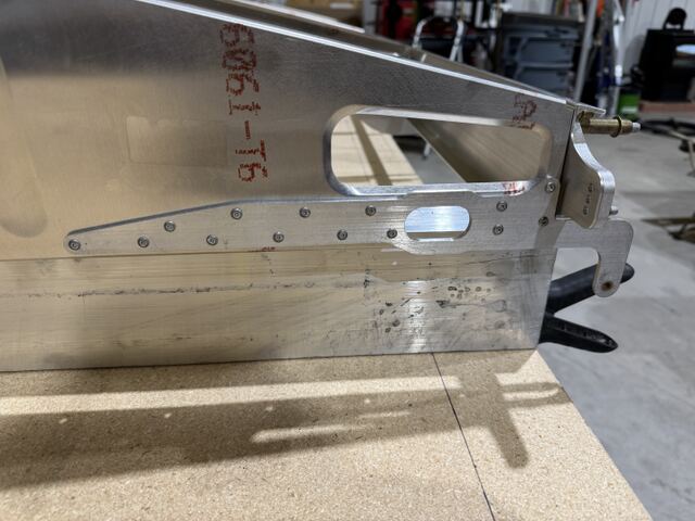
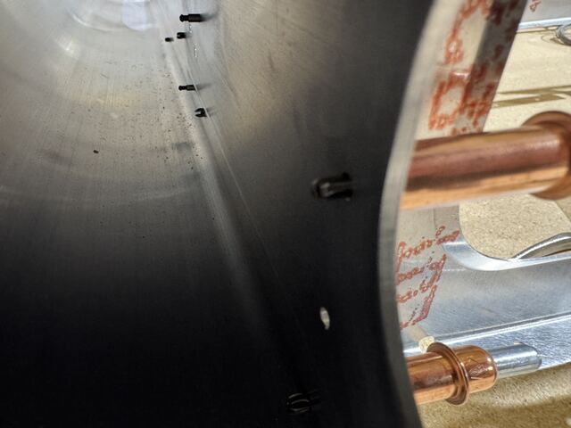
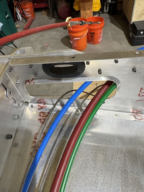
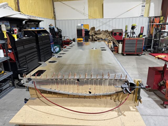
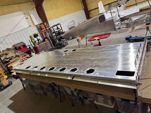
Wing fuel tank on the stand for a leak check

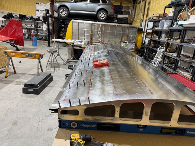
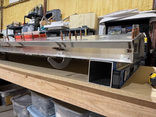
Set a wing fuel tank on a stand, part filled, for a leak check that was under way.

Methods. Hours approximate, entered later from dated photographs.

Plans reference. WING FUEL TANK ASSEMBLY, page 71, steps 13 to 18; FIGURE 06-14; parts manual 006D-02
  • Photograph from Wing fuel tank on the stand for a leak check
  • Photograph from Wing fuel tank on the stand for a leak check
  • Photograph from Wing fuel tank on the stand for a leak check

30 Jun 2026

Wings

Wing fuel tank on the stand for a leak check

Set a wing fuel tank on a stand, part filled, for a leak check that was under way.

Methods. Hours approximate, entered later from dated photographs.

Plans reference. WING FUEL TANK ASSEMBLY, page 71, steps 13 to 18; FIGURE 06-14; parts manual 006D-02
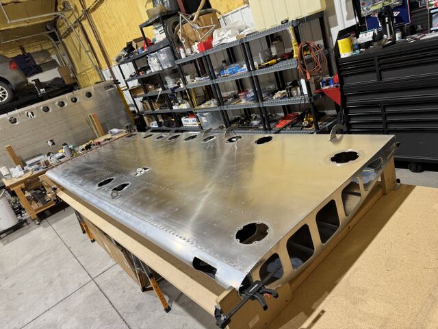
  • Photograph from Wing fuel tank on the stand for a leak check
  • Photograph from Wing fuel tank on the stand for a leak check
  • Photograph from Wing fuel tank on the stand for a leak check

30 Jun 2026

Wings

Wing fuel tank on the stand for a leak check

Set a wing fuel tank on a stand, part filled, for a leak check that was under way.

Methods. Hours approximate, entered later from dated photographs.

Plans reference. WING FUEL TANK ASSEMBLY, page 71, steps 13 to 18; FIGURE 06-14; parts manual 006D-02
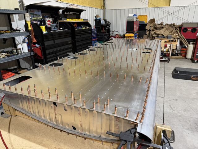
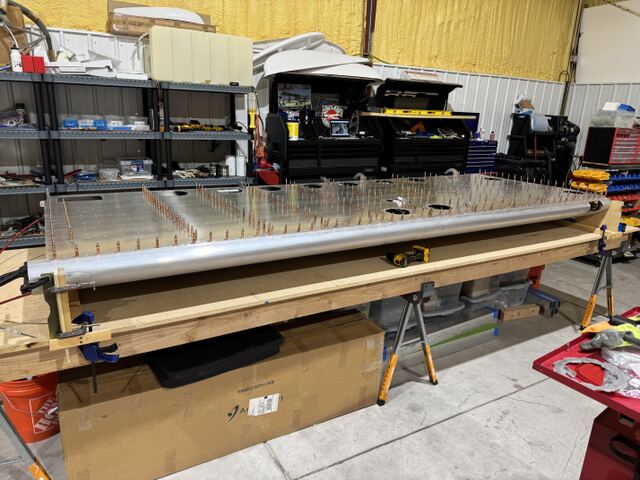
  • Photograph from Wing fuel tank on the stand for a leak check
  • Photograph from Wing fuel tank on the stand for a leak check
  • Photograph from Wing fuel tank on the stand for a leak check

30 Jun 2026

Wings

Wing fuel tank on the stand for a leak check

Set a wing fuel tank on a stand, part filled, for a leak check that was under way.

Methods. Hours approximate, entered later from dated photographs.

Plans reference. WING FUEL TANK ASSEMBLY, page 71, steps 13 to 18; FIGURE 06-14; parts manual 006D-02
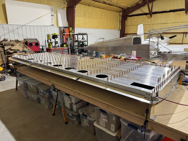
  • Photograph from Wing fuel tank on the stand for a leak check
  • Photograph from Wing fuel tank on the stand for a leak check
  • Photograph from Wing fuel tank on the stand for a leak check
  • Photograph from Wing fuel tank on the stand for a leak check

30 Jun 2026

Wings

Wing fuel tank on the stand for a leak check

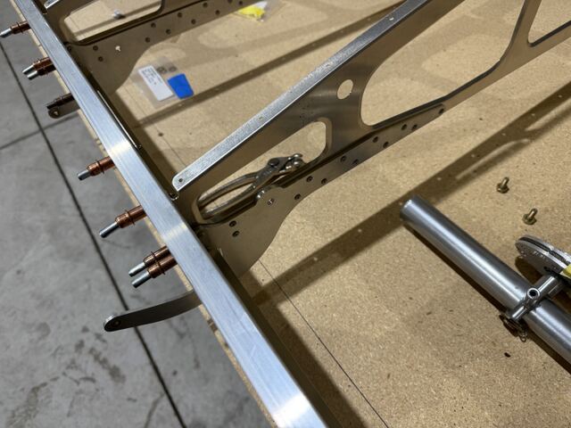
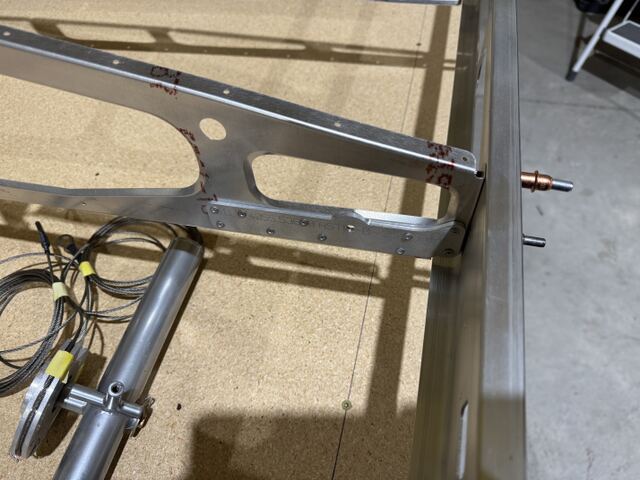
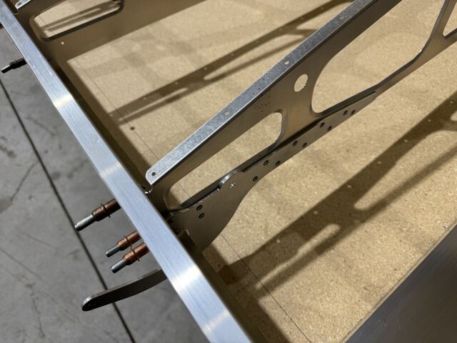
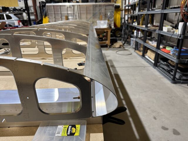
Set a wing fuel tank on a stand, part filled, for a leak check that was under way.

Methods. Hours approximate, entered later from dated photographs.

Plans reference. WING FUEL TANK ASSEMBLY, page 71, steps 13 to 18; FIGURE 06-14; parts manual 006D-02
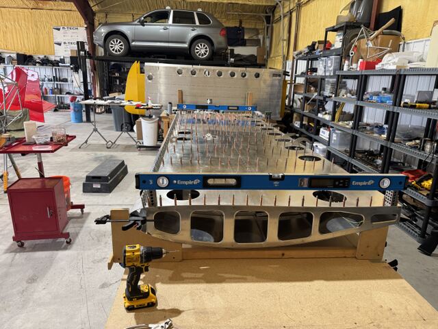
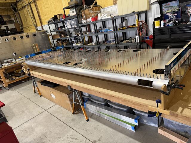
  • Photograph from Wing fuel tank on the stand for a leak check
  • Photograph from Wing fuel tank on the stand for a leak check

30 Jun 2026

Wings

Wing fuel tank on the stand for a leak check

Set a wing fuel tank on a stand, part filled, for a leak check that was under way.

Methods. Hours approximate, entered later from dated photographs.

Plans reference. WING FUEL TANK ASSEMBLY, page 71, steps 13 to 18; FIGURE 06-14; parts manual 006D-02
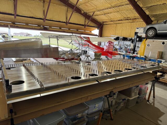
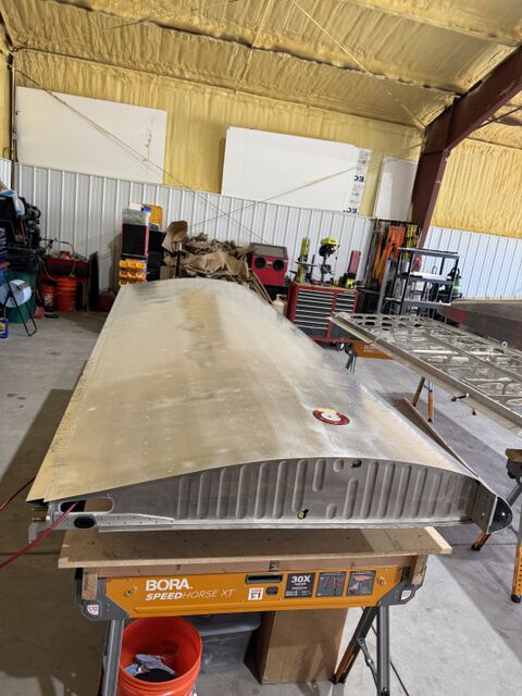
  • Photograph from Wing fuel tank on the stand for a leak check
  • Photograph from Wing fuel tank on the stand for a leak check
  • Photograph from Wing fuel tank on the stand for a leak check
  • Photograph from Wing fuel tank on the stand for a leak check

29 Jun 2026

Wings

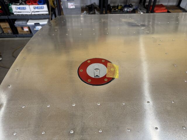
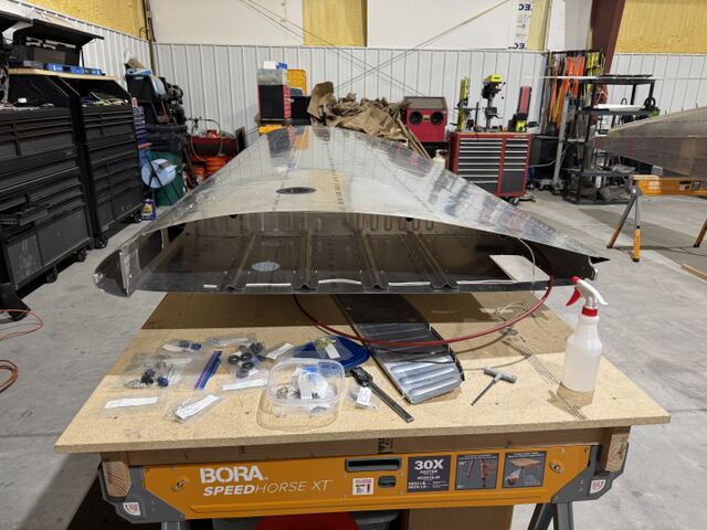
Wing top skin at the fuel filler

Methods. Hours approximate, entered later from dated photographs.
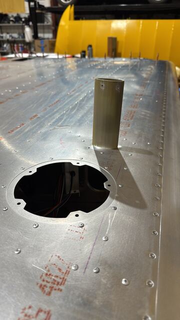
  • Photograph from Wing top skin at the fuel filler

5 May 2026

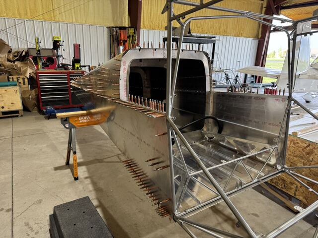
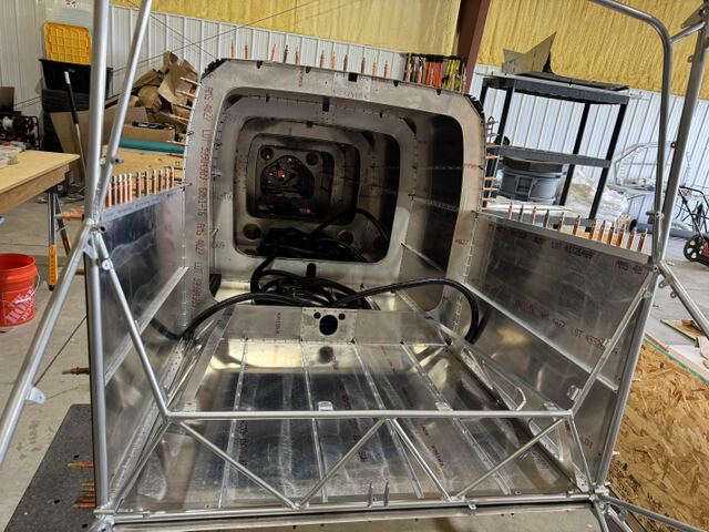
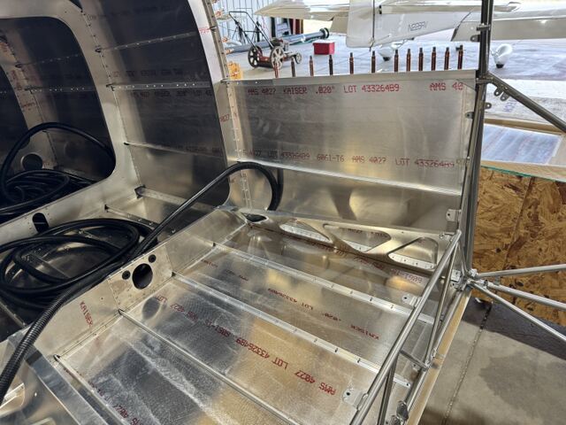
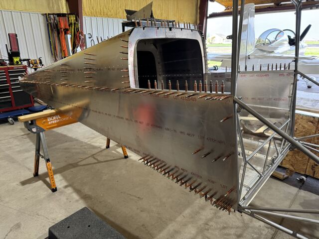
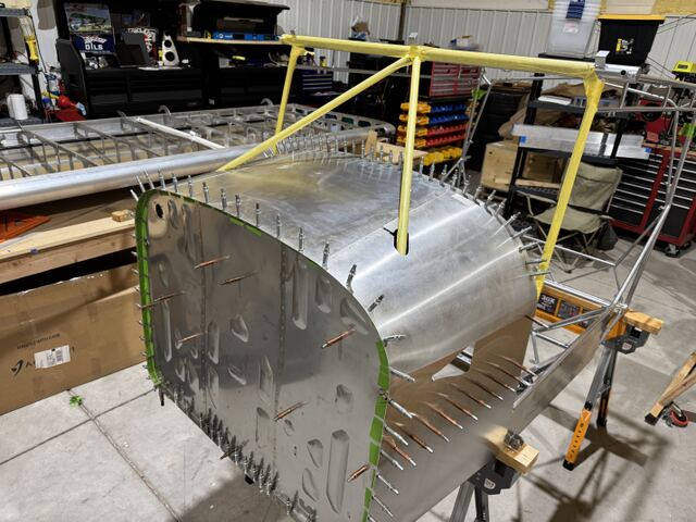
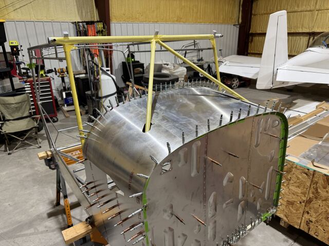
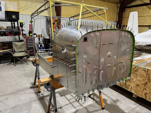
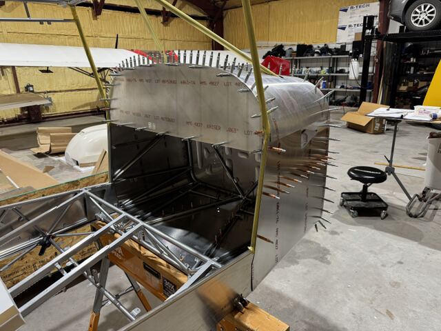
Fuselage

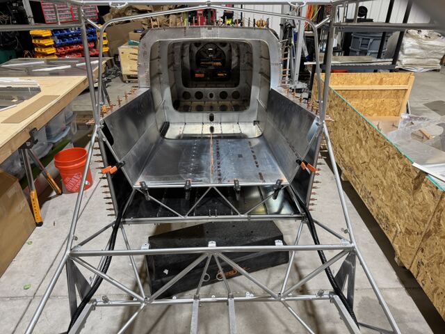
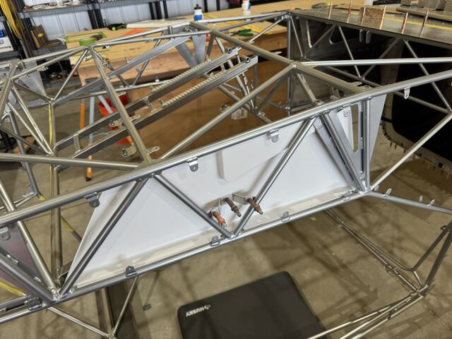
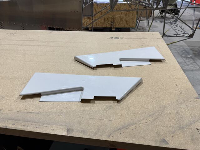
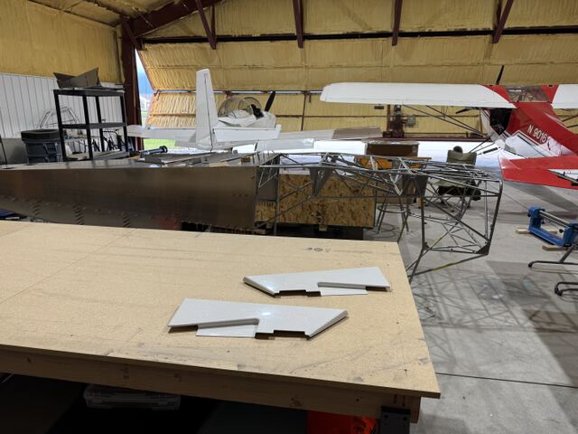
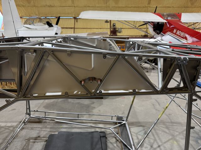
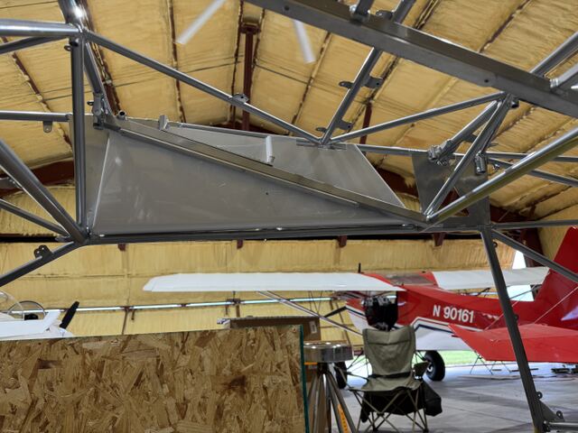
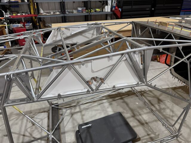
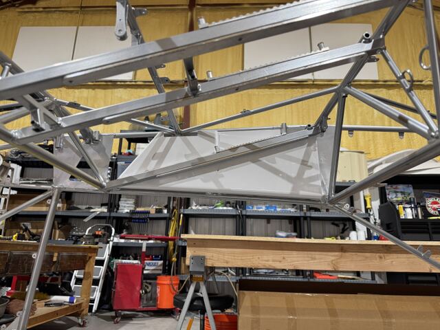
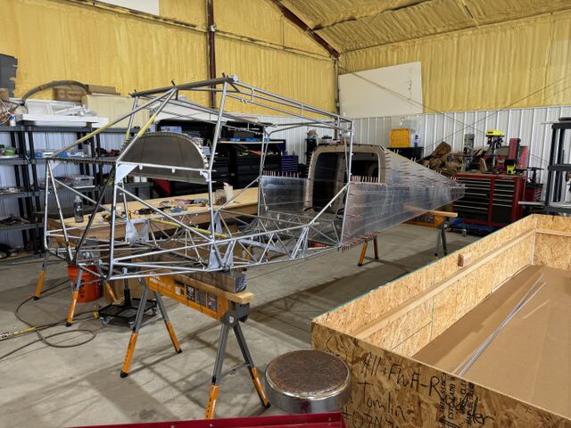
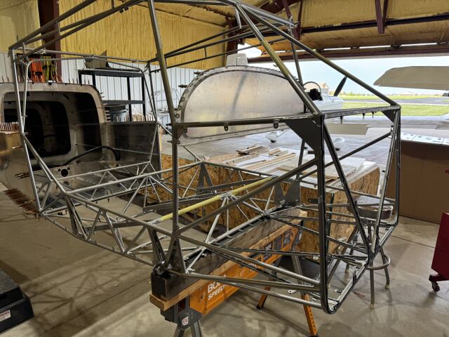
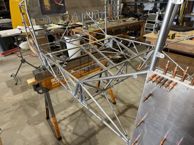
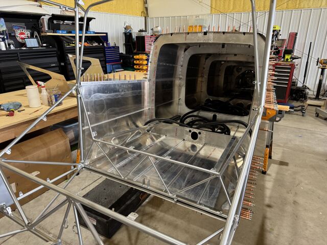
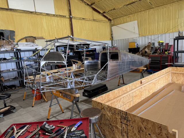
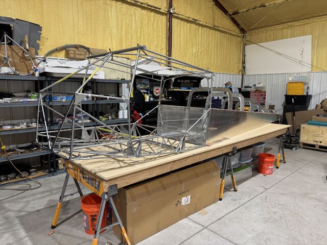
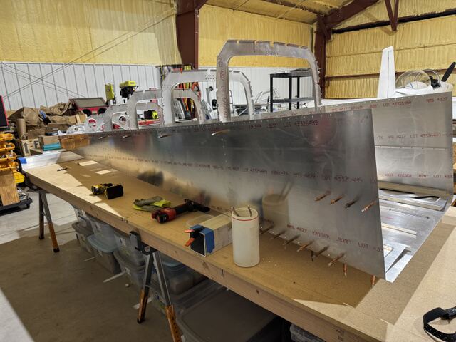
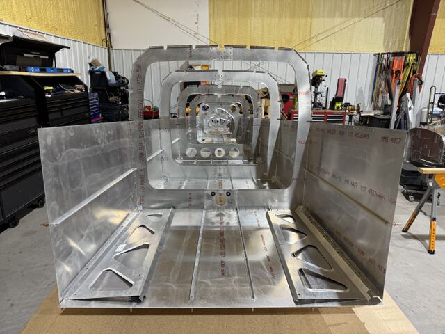
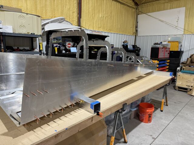
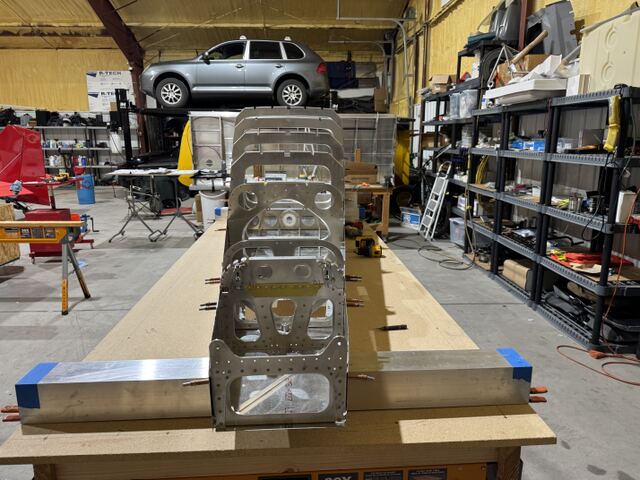
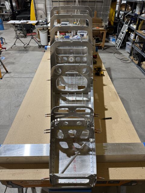
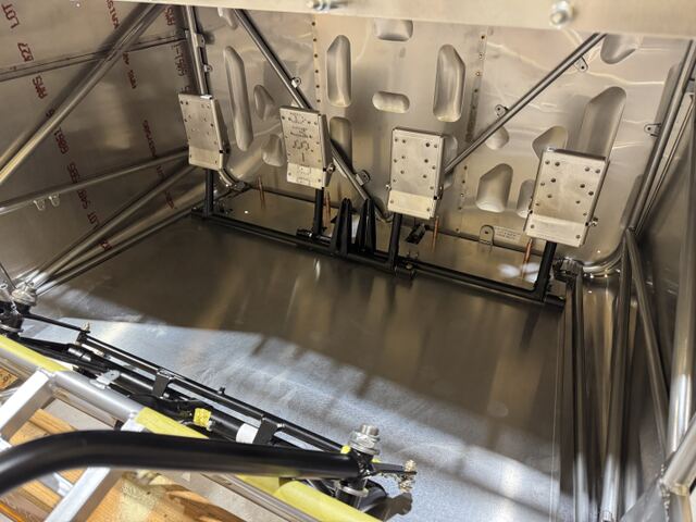
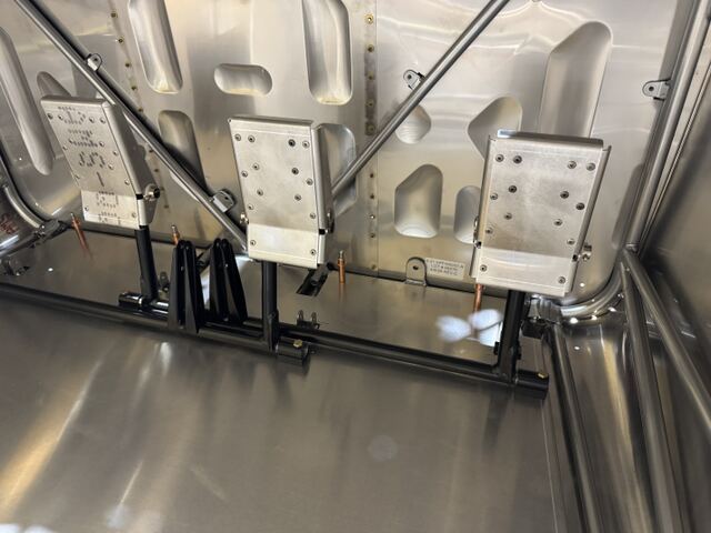
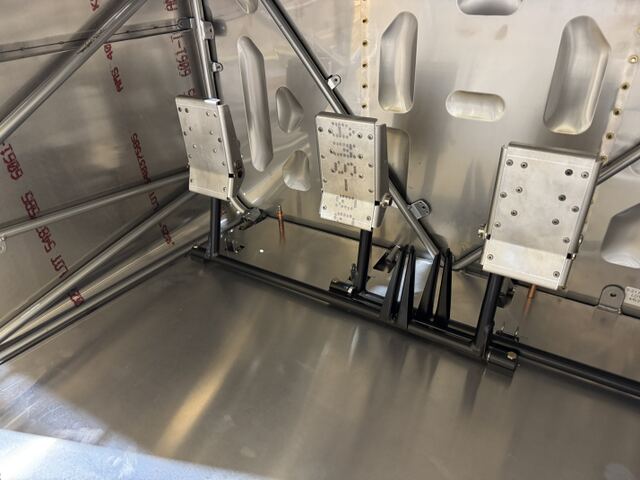
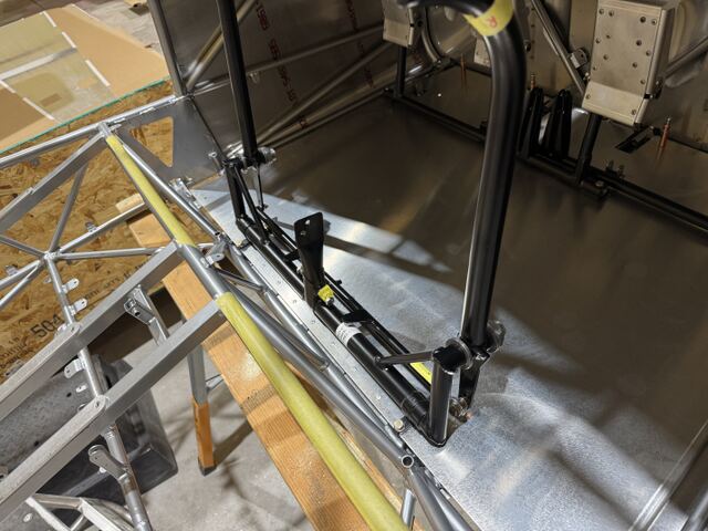
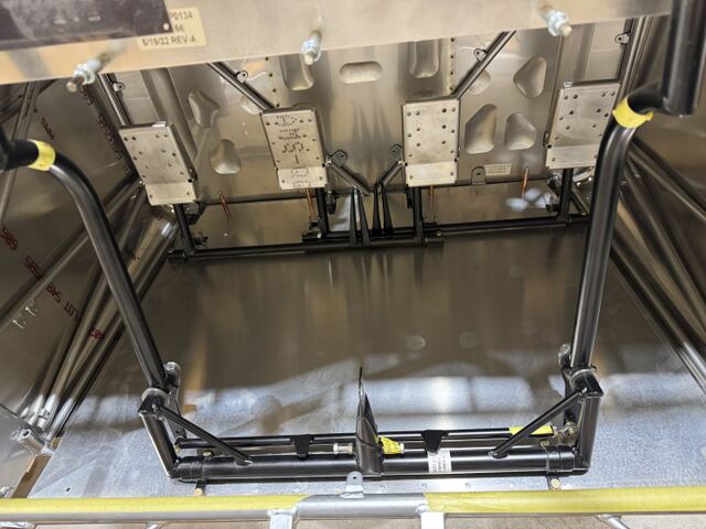
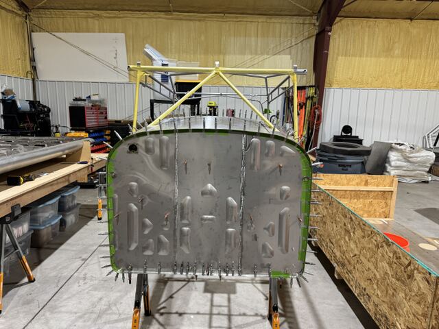
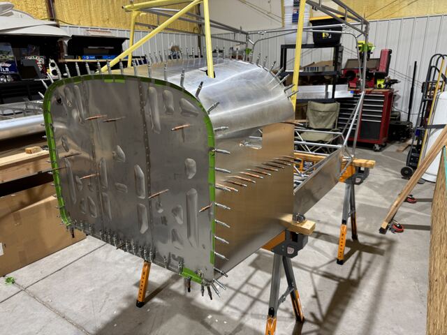
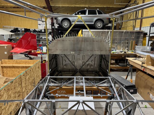
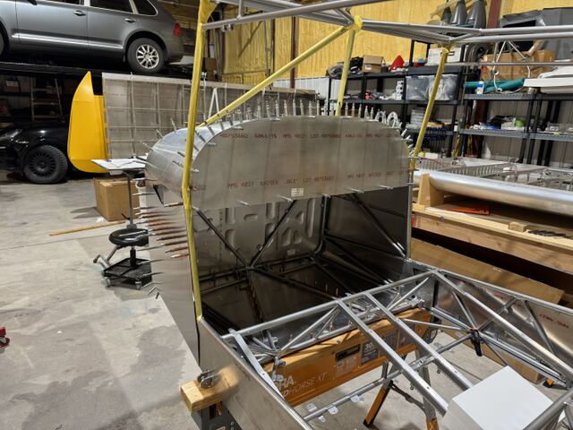
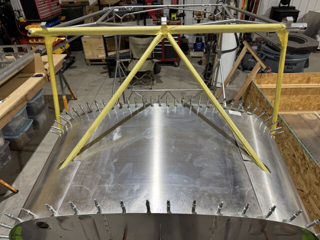
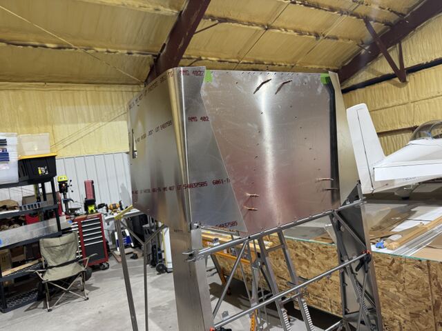
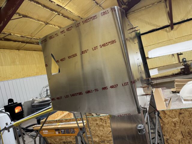
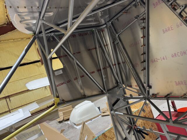
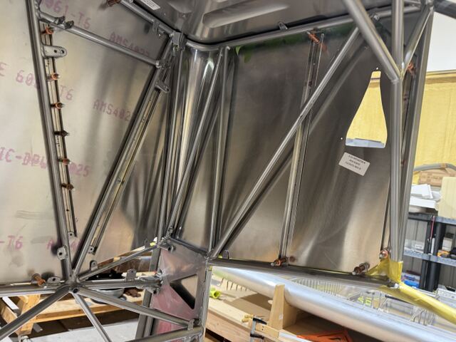
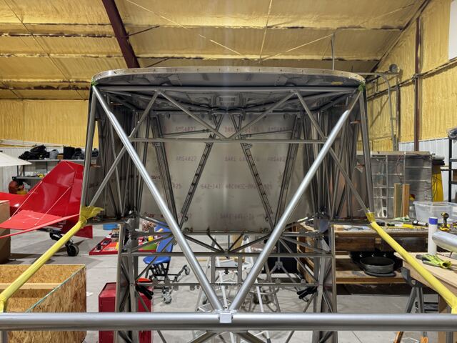
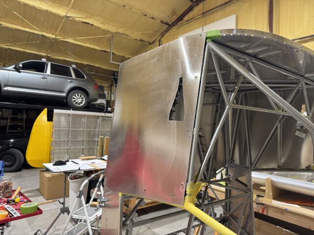
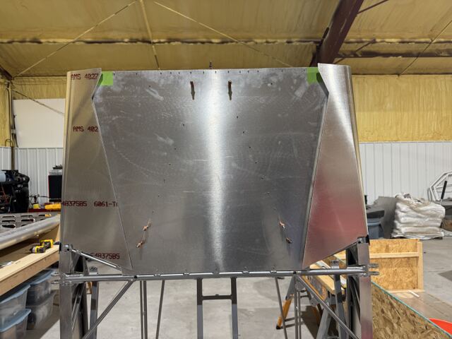
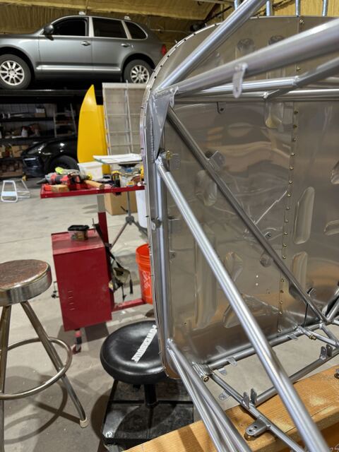
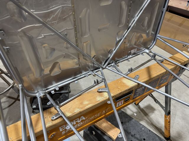
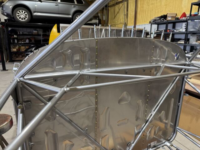
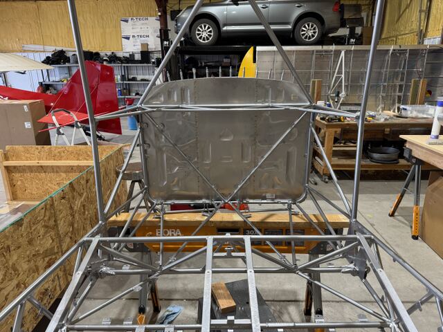
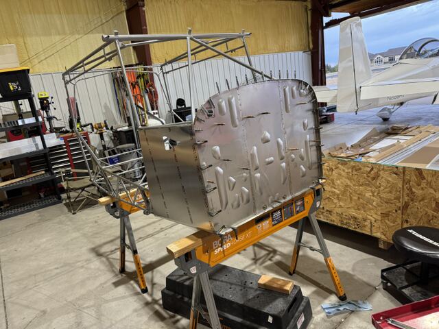
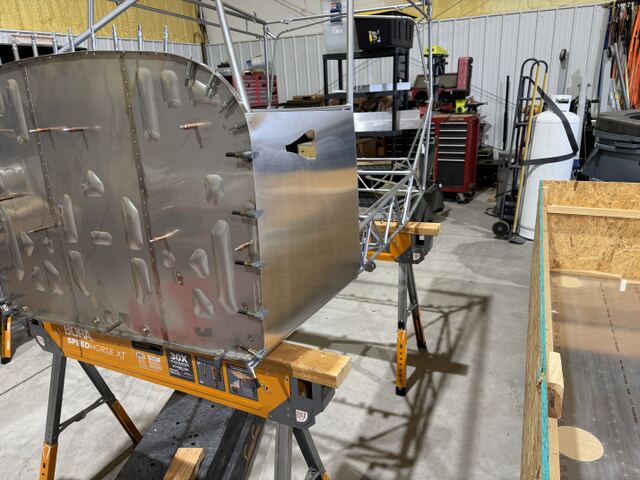
Rebuilding of the cage

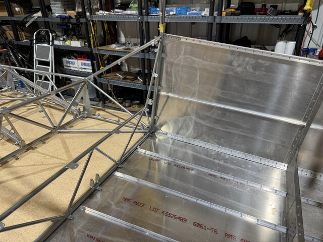
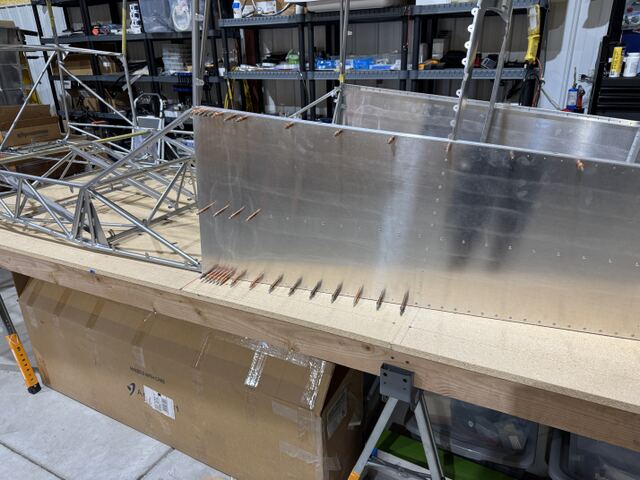
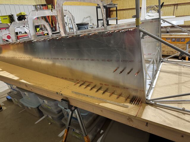
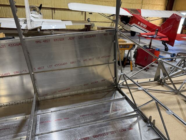
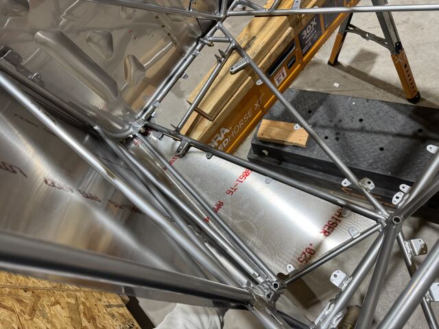
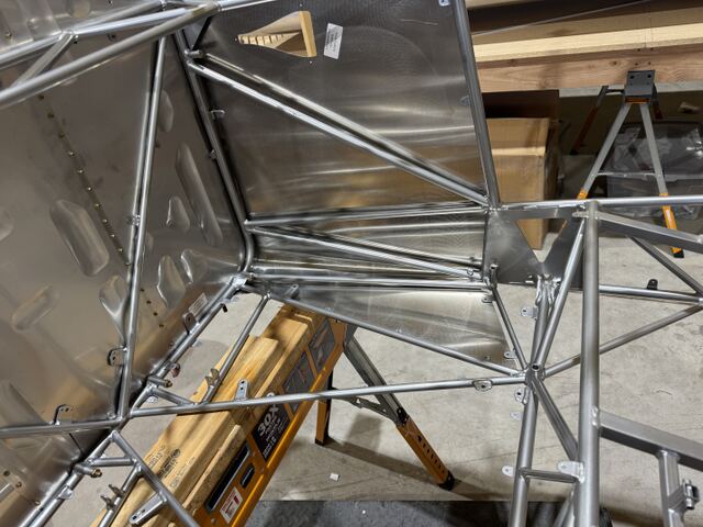
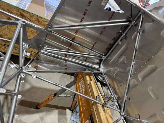
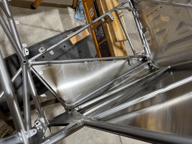
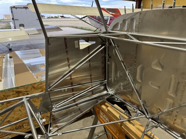
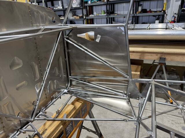
More work on the cage: fitted, drilled and clecoed the firewall, the boot cowl and the forward fuselage floor.

Methods. Hours approximate, entered later from dated photographs.

Plans reference. BOOT COWL ASSEMBLY, page 94 to 95; FLOORBOARD INSTALLATION, page 103; FIGURE 10E-11; parts manual 010E-02; parts manual 009-02
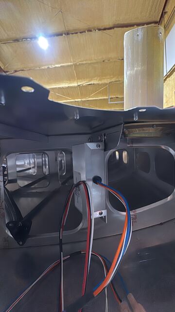
  • Photograph from Rebuilding of the cage

5 May 2026

Fuselage

Rebuilding of the cage

More work on the cage: fitted, drilled and clecoed the firewall, the boot cowl and the forward fuselage floor.

Methods. Hours approximate, entered later from dated photographs.

Plans reference. BOOT COWL ASSEMBLY, page 94 to 95; FLOORBOARD INSTALLATION, page 103; FIGURE 10E-11; parts manual 010E-02; parts manual 009-02
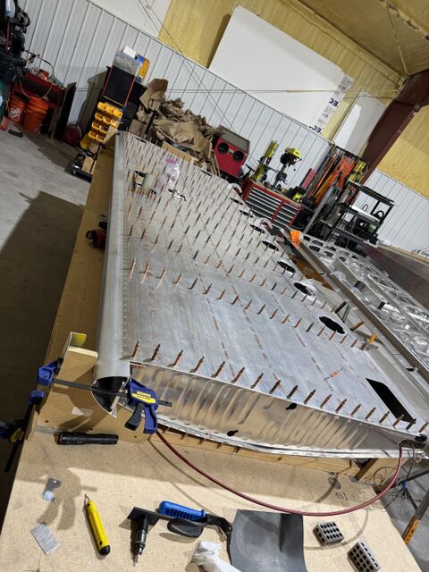
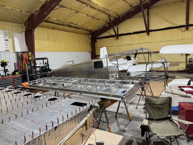
  • Photograph from Rebuilding of the cage
  • Photograph from Rebuilding of the cage
  • Photograph from Rebuilding of the cage
  • Photograph from Rebuilding of the cage
  • Photograph from Rebuilding of the cage
  • Photograph from Rebuilding of the cage

5 May 2026

Fuselage

Rebuilding of the cage

More work on the cage: fitted, drilled and clecoed the firewall, the boot cowl and the forward fuselage floor.

Methods. Hours approximate, entered later from dated photographs.

Plans reference. BOOT COWL ASSEMBLY, page 94 to 95; FLOORBOARD INSTALLATION, page 103; FIGURE 10E-11; parts manual 010E-02; parts manual 009-02
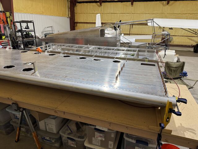
  • Photograph from Rebuilding of the cage

5 May 2026

Fuselage

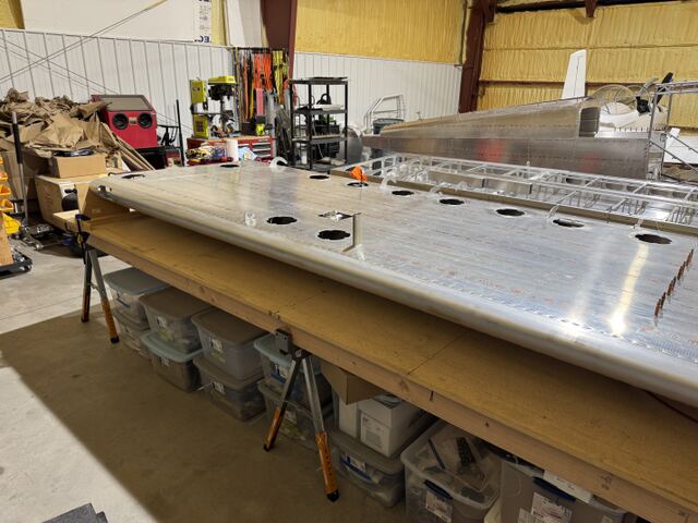
Rebuilding of the cage

More work on the cage: fitted, drilled and clecoed the firewall, the boot cowl and the forward fuselage floor.

Methods. Hours approximate, entered later from dated photographs.

Plans reference. BOOT COWL ASSEMBLY, page 94 to 95; FLOORBOARD INSTALLATION, page 103; FIGURE 10E-11; parts manual 010E-02; parts manual 009-02
  • Photograph from Rebuilding of the cage
  • Photograph from Rebuilding of the cage
  • Photograph from Rebuilding of the cage

5 May 2026

Fuselage

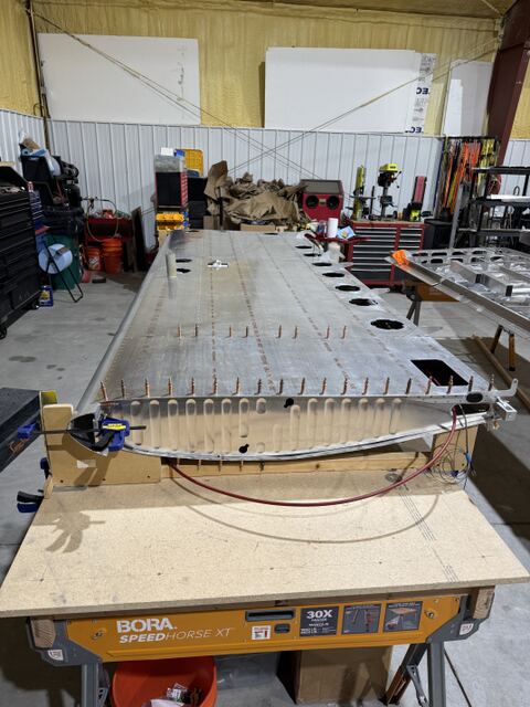
Rebuilding of the cage

More work on the cage: fitted, drilled and clecoed the firewall, the boot cowl and the forward fuselage floor.

Methods. Hours approximate, entered later from dated photographs.

Plans reference. BOOT COWL ASSEMBLY, page 94 to 95; FLOORBOARD INSTALLATION, page 103; FIGURE 10E-11; parts manual 010E-02; parts manual 009-02
  • Photograph from Rebuilding of the cage
  • Photograph from Rebuilding of the cage
  • Photograph from Rebuilding of the cage
  • Photograph from Rebuilding of the cage
  • Photograph from Rebuilding of the cage
  • Photograph from Rebuilding of the cage
  • Photograph from Rebuilding of the cage
  • Photograph from Rebuilding of the cage
  • Photograph from Rebuilding of the cage

5 May 2026

Fuselage

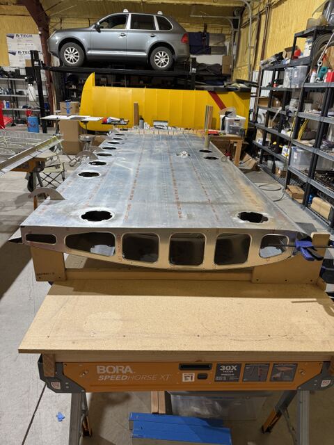
Rebuilding of the cage

More work on the cage: fitted, drilled and clecoed the firewall, the boot cowl and the forward fuselage floor.

Methods. Hours approximate, entered later from dated photographs.

Plans reference. BOOT COWL ASSEMBLY, page 94 to 95; FLOORBOARD INSTALLATION, page 103; FIGURE 10E-11; parts manual 010E-02; parts manual 009-02
  • Photograph from Rebuilding of the cage

5 May 2026

Fuselage

Rebuilding of the cage

More work on the cage: fitted, drilled and clecoed the firewall, the boot cowl and the forward fuselage floor.

Methods. Hours approximate, entered later from dated photographs.

Plans reference. BOOT COWL ASSEMBLY, page 94 to 95; FLOORBOARD INSTALLATION, page 103; FIGURE 10E-11; parts manual 010E-02; parts manual 009-02
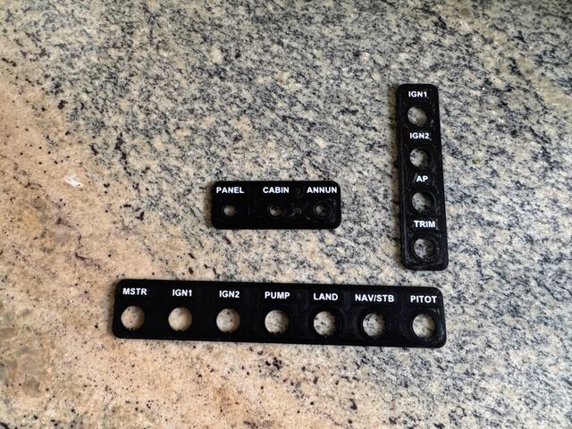
  • Photograph from Rebuilding of the cage
  • Photograph from Rebuilding of the cage
  • Photograph from Rebuilding of the cage
  • Photograph from Rebuilding of the cage
  • Photograph from Rebuilding of the cage
  • Photograph from Rebuilding of the cage
  • Photograph from Rebuilding of the cage
  • Photograph from Rebuilding of the cage

5 May 2026

Fuselage

Rebuilding of the cage

More work on the cage: fitted, drilled and clecoed the firewall, the boot cowl and the forward fuselage floor.

Methods. Hours approximate, entered later from dated photographs.

Plans reference. BOOT COWL ASSEMBLY, page 94 to 95; FLOORBOARD INSTALLATION, page 103; FIGURE 10E-11; parts manual 010E-02; parts manual 009-02
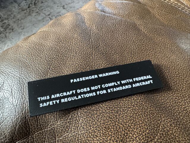
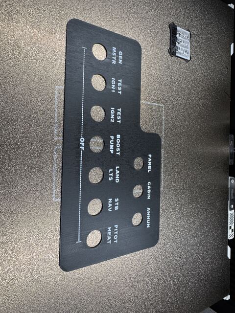
  • Photograph from Rebuilding of the cage
  • Photograph from Rebuilding of the cage
  • Photograph from Rebuilding of the cage
  • Photograph from Rebuilding of the cage
  • Photograph from Rebuilding of the cage
  • Photograph from Rebuilding of the cage
  • Photograph from Rebuilding of the cage
  • Photograph from Rebuilding of the cage
  • Photograph from Rebuilding of the cage
  • Photograph from Rebuilding of the cage
  • Photograph from Rebuilding of the cage
  • Photograph from Rebuilding of the cage
  • Photograph from Rebuilding of the cage
  • Photograph from Rebuilding of the cage
  • Photograph from Rebuilding of the cage
  • Photograph from Rebuilding of the cage
  • Photograph from Rebuilding of the cage

5 May 2026

Fuselage

Rebuilding of the cage

More work on the cage: fitted, drilled and clecoed the firewall, the boot cowl and the forward fuselage floor.

Methods. Hours approximate, entered later from dated photographs.

Plans reference. BOOT COWL ASSEMBLY, page 94 to 95; FLOORBOARD INSTALLATION, page 103; FIGURE 10E-11; parts manual 010E-02; parts manual 009-02
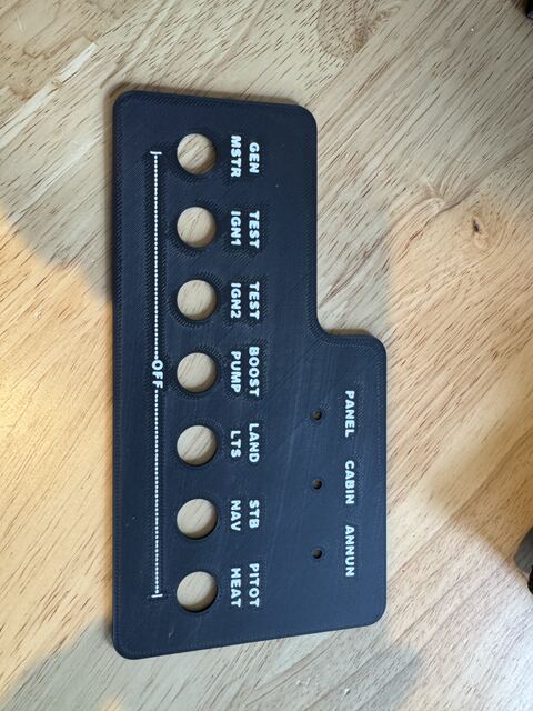
  • Photograph from Rebuilding of the cage
  • Photograph from Rebuilding of the cage
  • Photograph from Rebuilding of the cage
  • Photograph from Rebuilding of the cage
  • Photograph from Rebuilding of the cage

5 May 2026

Fuselage

Rebuilding of the cage

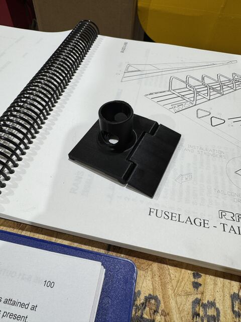
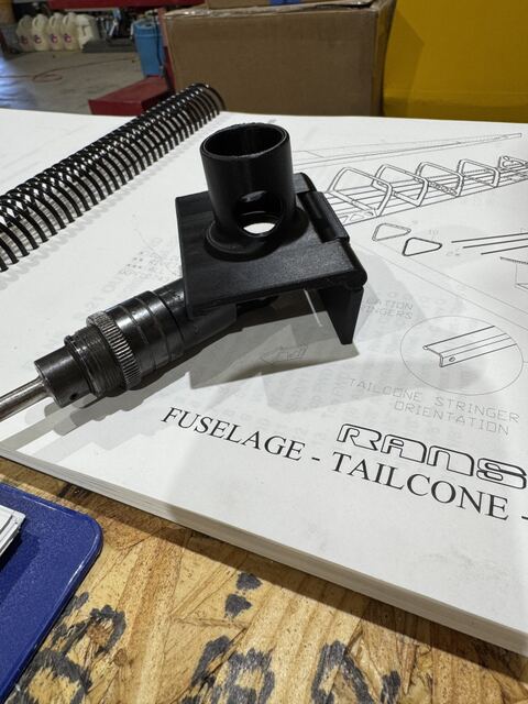
More work on the cage: fitted, drilled and clecoed the firewall, the boot cowl and the forward fuselage floor.

Methods. Hours approximate, entered later from dated photographs.

Plans reference. BOOT COWL ASSEMBLY, page 94 to 95; FLOORBOARD INSTALLATION, page 103; FIGURE 10E-11; parts manual 010E-02; parts manual 009-02
  • Photograph from Rebuilding of the cage
  • Photograph from Rebuilding of the cage
  • Photograph from Rebuilding of the cage
  • Photograph from Rebuilding of the cage
  • Photograph from Rebuilding of the cage

5 May 2026

Fuselage

Rebuilding of the cage

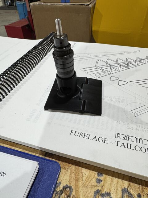
More work on the cage: fitted, drilled and clecoed the firewall, the boot cowl and the forward fuselage floor.

Methods. Hours approximate, entered later from dated photographs.

Plans reference. BOOT COWL ASSEMBLY, page 94 to 95; FLOORBOARD INSTALLATION, page 103; FIGURE 10E-11; parts manual 010E-02; parts manual 009-02
  • Photograph from Rebuilding of the cage
  • Photograph from Rebuilding of the cage
  • Photograph from Rebuilding of the cage
  • Photograph from Rebuilding of the cage
  • Photograph from Rebuilding of the cage

5 May 2026

Fuselage

Rebuilding of the cage

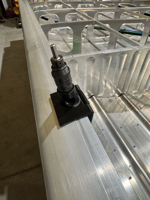
More work on the cage: fitted, drilled and clecoed the firewall, the boot cowl and the forward fuselage floor.

Methods. Hours approximate, entered later from dated photographs.

Plans reference. BOOT COWL ASSEMBLY, page 94 to 95; FLOORBOARD INSTALLATION, page 103; FIGURE 10E-11; parts manual 010E-02; parts manual 009-02
  • Photograph from Rebuilding of the cage
  • Photograph from Rebuilding of the cage
  • Photograph from Rebuilding of the cage
  • Photograph from Rebuilding of the cage
  • Photograph from Rebuilding of the cage
  • Photograph from Rebuilding of the cage
  • Photograph from Rebuilding of the cage
  • Photograph from Rebuilding of the cage
  • Photograph from Rebuilding of the cage

5 May 2026

Fuselage

Rebuilding of the cage

More work on the cage: fitted, drilled and clecoed the firewall, the boot cowl and the forward fuselage floor.

Methods. Hours approximate, entered later from dated photographs.

Plans reference. BOOT COWL ASSEMBLY, page 94 to 95; FLOORBOARD INSTALLATION, page 103; FIGURE 10E-11; parts manual 010E-02; parts manual 009-02
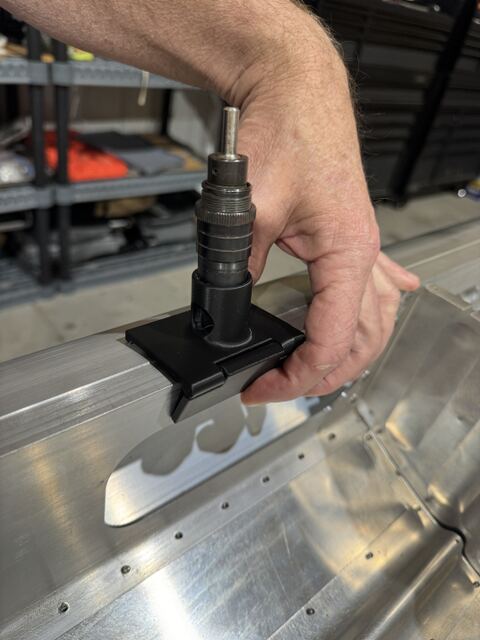
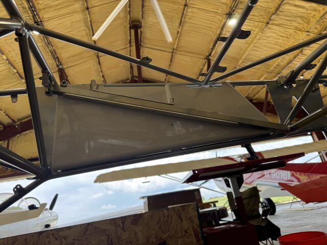
  • Photograph from Rebuilding of the cage
  • Photograph from Rebuilding of the cage
  • Photograph from Rebuilding of the cage
  • Photograph from Rebuilding of the cage
  • Photograph from Rebuilding of the cage
  • Photograph from Rebuilding of the cage
  • Photograph from Rebuilding of the cage

3 May 2026

Wings

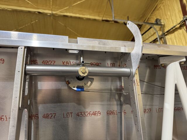
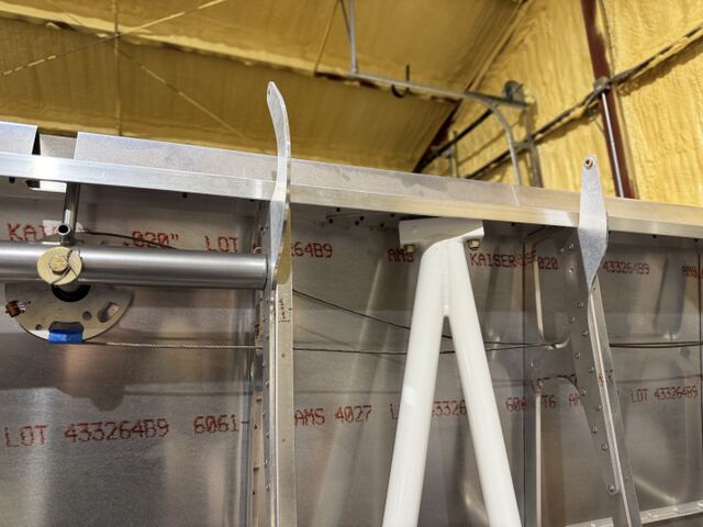
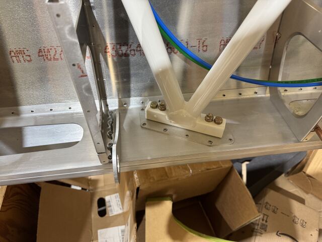
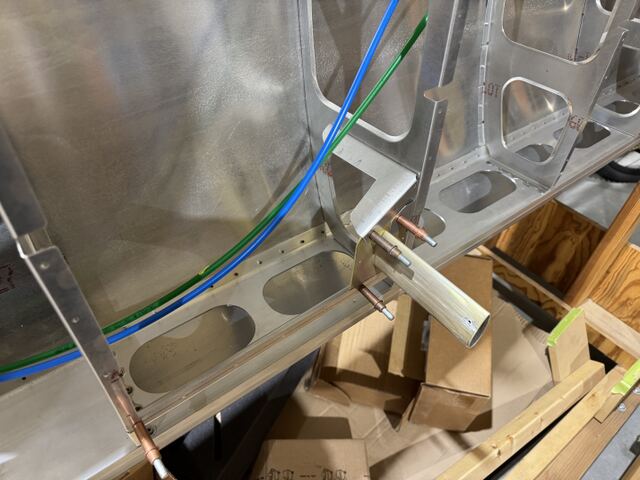
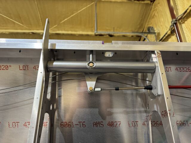
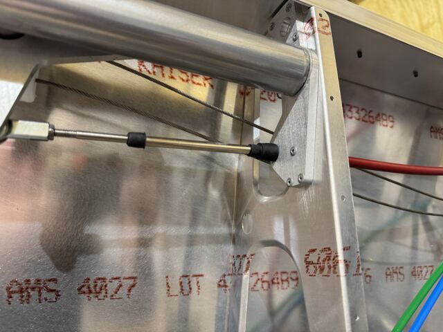
Installed the right wing bellcranks, cables and conduit

Flipped the right wing over and installed the aileron bellcrank and cables, the flap bellcrank and Teleflex cable, and the wiring conduit.

Methods. Hours approximate, entered later from dated photographs.

Plans reference. AILERON BELLCRANK ASSEMBLY, page 59; FLAP BELLCRANK ASSEMBLY, page 60; WING RIB / SPAR ASSEMBLY, page 63
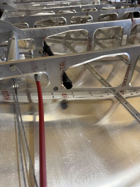
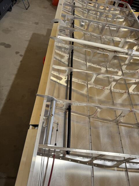
  • Photograph from Installed the right wing bellcranks, cables and conduit
  • Photograph from Installed the right wing bellcranks, cables and conduit

13 Apr 2026

Wings

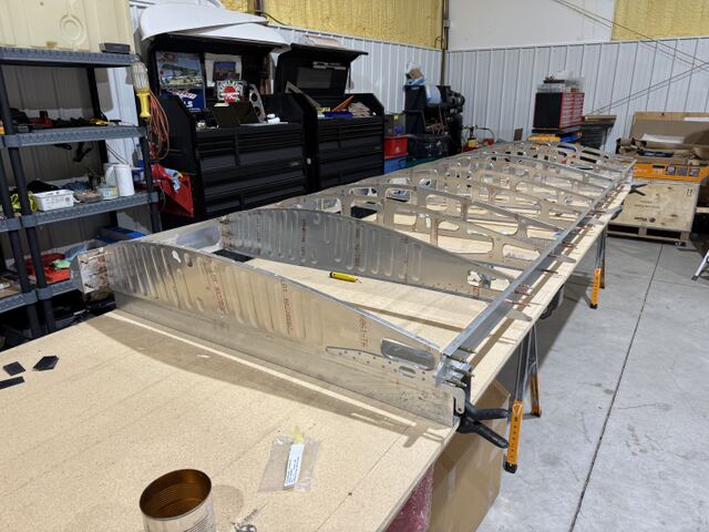
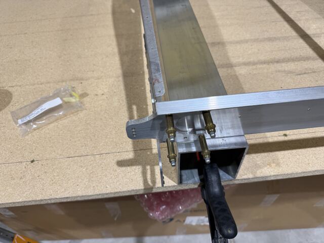
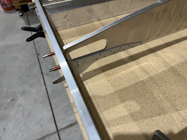
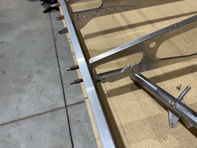
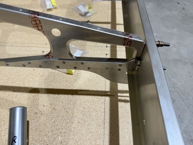
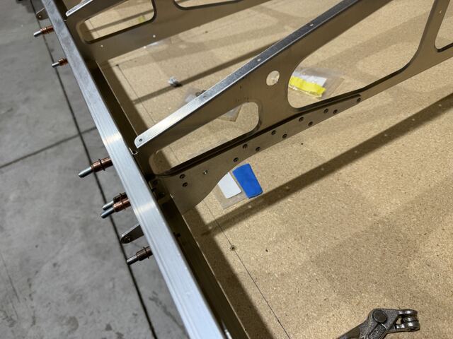
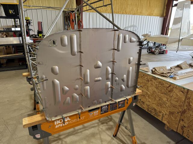
Assembled the right wing ribs and spar

Built the right wing: fitted the ribs to the spar, and checked for the proper rivet length for the extruded forward D spar. No bellcranks, cables or tubing in it yet.

Methods. Hours approximate, entered later from dated photographs.

Plans reference. WING RIB / SPAR ASSEMBLY, page 61 to 63; FIGURE 06-01; parts manual 006B-02
  • Photograph from Assembled the right wing ribs and spar
  • Photograph from Assembled the right wing ribs and spar
  • Photograph from Assembled the right wing ribs and spar
  • Photograph from Assembled the right wing ribs and spar
  • Photograph from Assembled the right wing ribs and spar
  • Photograph from Assembled the right wing ribs and spar
  • Photograph from Assembled the right wing ribs and spar
  • Photograph from Assembled the right wing ribs and spar
  • Photograph from Assembled the right wing ribs and spar
  • Photograph from Assembled the right wing ribs and spar
  • Photograph from Assembled the right wing ribs and spar
  • Photograph from Assembled the right wing ribs and spar
  • Photograph from Assembled the right wing ribs and spar
  • Photograph from Assembled the right wing ribs and spar
  • Photograph from Assembled the right wing ribs and spar
  • Photograph from Assembled the right wing ribs and spar
  • Photograph from Assembled the right wing ribs and spar

13 Apr 2026

Wings

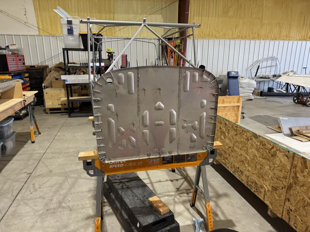
Assembled the right wing ribs and spar

Built the right wing: fitted the ribs to the spar, and checked for the proper rivet length for the extruded forward D spar. No bellcranks, cables or tubing in it yet.

Methods. Hours approximate, entered later from dated photographs.

Plans reference. WING RIB / SPAR ASSEMBLY, page 61 to 63; FIGURE 06-01; parts manual 006B-02
  • Photograph from Assembled the right wing ribs and spar
  • Photograph from Assembled the right wing ribs and spar
  • Photograph from Assembled the right wing ribs and spar
  • Photograph from Assembled the right wing ribs and spar
  • Photograph from Assembled the right wing ribs and spar
  • Photograph from Assembled the right wing ribs and spar
  • Photograph from Assembled the right wing ribs and spar
  • Photograph from Assembled the right wing ribs and spar
  • Photograph from Assembled the right wing ribs and spar
  • Photograph from Assembled the right wing ribs and spar
  • Photograph from Assembled the right wing ribs and spar
  • Photograph from Assembled the right wing ribs and spar
  • Photograph from Assembled the right wing ribs and spar
  • Photograph from Assembled the right wing ribs and spar
  • Photograph from Assembled the right wing ribs and spar
  • Photograph from Assembled the right wing ribs and spar
  • Photograph from Assembled the right wing ribs and spar

13 Apr 2026

Wings

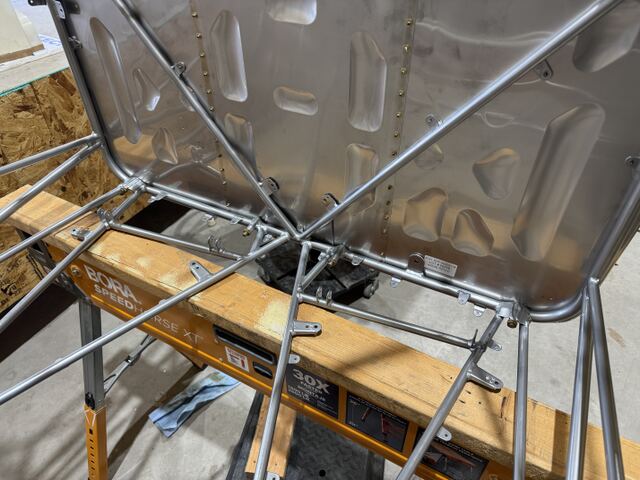
Assembled the right wing ribs and spar

Built the right wing: fitted the ribs to the spar, and checked for the proper rivet length for the extruded forward D spar. No bellcranks, cables or tubing in it yet.

Methods. Hours approximate, entered later from dated photographs.

Plans reference. WING RIB / SPAR ASSEMBLY, page 61 to 63; FIGURE 06-01; parts manual 006B-02
  • Photograph from Assembled the right wing ribs and spar
  • Photograph from Assembled the right wing ribs and spar
  • Photograph from Assembled the right wing ribs and spar
  • Photograph from Assembled the right wing ribs and spar
  • Photograph from Assembled the right wing ribs and spar
  • Photograph from Assembled the right wing ribs and spar
  • Photograph from Assembled the right wing ribs and spar
  • Photograph from Assembled the right wing ribs and spar
  • Photograph from Assembled the right wing ribs and spar
  • Photograph from Assembled the right wing ribs and spar
  • Photograph from Assembled the right wing ribs and spar
  • Photograph from Assembled the right wing ribs and spar
  • Photograph from Assembled the right wing ribs and spar
  • Photograph from Assembled the right wing ribs and spar
  • Photograph from Assembled the right wing ribs and spar
  • Photograph from Assembled the right wing ribs and spar
  • Photograph from Assembled the right wing ribs and spar
  • Photograph from Assembled the right wing ribs and spar

13 Apr 2026

Wings

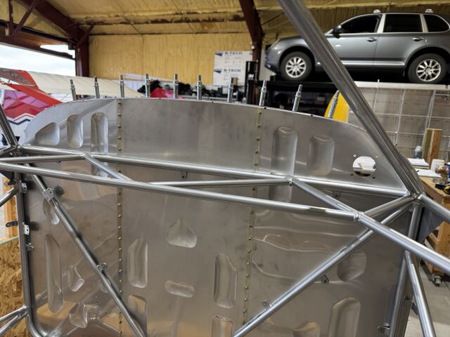
Assembled the right wing ribs and spar

Built the right wing: fitted the ribs to the spar, and checked for the proper rivet length for the extruded forward D spar. No bellcranks, cables or tubing in it yet.

Methods. Hours approximate, entered later from dated photographs.

Plans reference. WING RIB / SPAR ASSEMBLY, page 61 to 63; FIGURE 06-01; parts manual 006B-02
  • Photograph from Assembled the right wing ribs and spar
  • Photograph from Assembled the right wing ribs and spar
  • Photograph from Assembled the right wing ribs and spar
  • Photograph from Assembled the right wing ribs and spar
  • Photograph from Assembled the right wing ribs and spar
  • Photograph from Assembled the right wing ribs and spar
  • Photograph from Assembled the right wing ribs and spar
  • Photograph from Assembled the right wing ribs and spar
  • Photograph from Assembled the right wing ribs and spar
  • Photograph from Assembled the right wing ribs and spar
  • Photograph from Assembled the right wing ribs and spar
  • Photograph from Assembled the right wing ribs and spar
  • Photograph from Assembled the right wing ribs and spar

13 Apr 2026

Wings

Assembled the right wing ribs and spar

Built the right wing: fitted the ribs to the spar, and checked for the proper rivet length for the extruded forward D spar. No bellcranks, cables or tubing in it yet.

Methods. Hours approximate, entered later from dated photographs.

Plans reference. WING RIB / SPAR ASSEMBLY, page 61 to 63; FIGURE 06-01; parts manual 006B-02
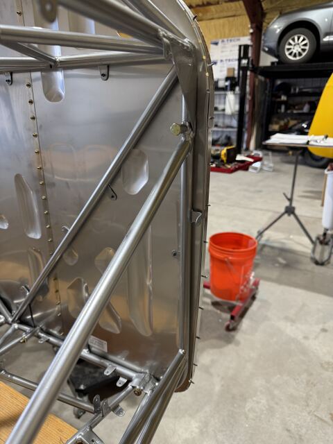
  • Photograph from Assembled the right wing ribs and spar
  • Photograph from Assembled the right wing ribs and spar
  • Photograph from Assembled the right wing ribs and spar
  • Photograph from Assembled the right wing ribs and spar
  • Photograph from Assembled the right wing ribs and spar
  • Photograph from Assembled the right wing ribs and spar
  • Photograph from Assembled the right wing ribs and spar
  • Photograph from Assembled the right wing ribs and spar
  • Photograph from Assembled the right wing ribs and spar
  • Photograph from Assembled the right wing ribs and spar
  • Photograph from Assembled the right wing ribs and spar
  • Photograph from Assembled the right wing ribs and spar
  • Photograph from Assembled the right wing ribs and spar
  • Photograph from Assembled the right wing ribs and spar
  • Photograph from Assembled the right wing ribs and spar

4 Apr 2026

Wings

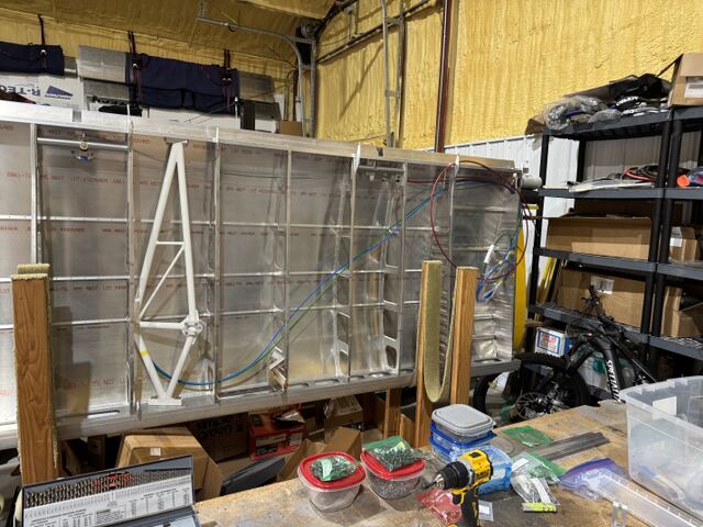
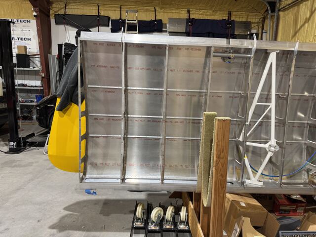
Inspected the left wing as received

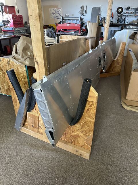
Inspected the left wing, which came about half built, in the wing rack: the bellcranks and cables already installed, and what was already run through the ribs (the pitot and static tubing, the aileron cables, and the flap Teleflex cable).

Methods. Hours approximate, entered later from dated photographs.
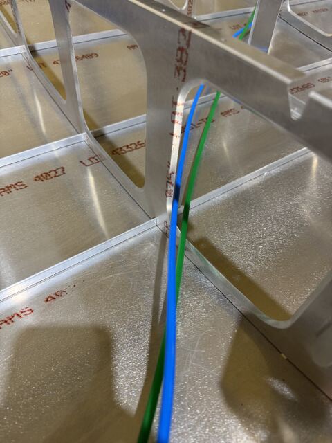
  • Photograph from Inspected the left wing as received
  • Photograph from Inspected the left wing as received
  • Photograph from Inspected the left wing as received
  • Photograph from Inspected the left wing as received
  • Photograph from Inspected the left wing as received
  • Photograph from Inspected the left wing as received
  • Photograph from Inspected the left wing as received
  • Photograph from Inspected the left wing as received
  • Photograph from Inspected the left wing as received
  • Photograph from Inspected the left wing as received
  • Photograph from Inspected the left wing as received

4 Apr 2026

Electrical and avionics

Unpacked and inventoried the kit

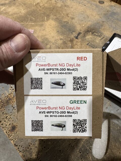
Unpacked the kit and inventoried the parts, including the wingtip strobes that came with it.

Methods. Hours approximate, entered later from dated photographs.
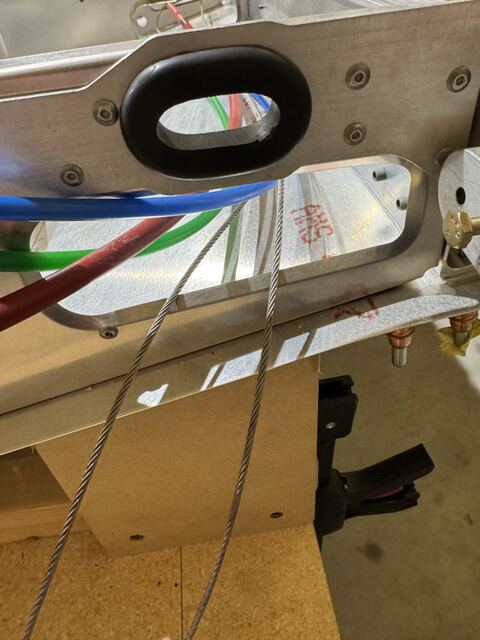
  • Photograph from Unpacked and inventoried the kit

2 Apr 2026

Delivery or pickup

Picked up the partially build kit

Drove up to Greely CO to pick up the kit from Tom

Methods. Large trailer and lots of supplies.

Lesson learned. A trailer can never be too big!

25 Mar 2026

Delivery or pickup

Looked over the kit before buying it

Looked over the partly built kit at the seller's: the fuselage cage, a tailcone section, the wing parts, and one wing about half built.
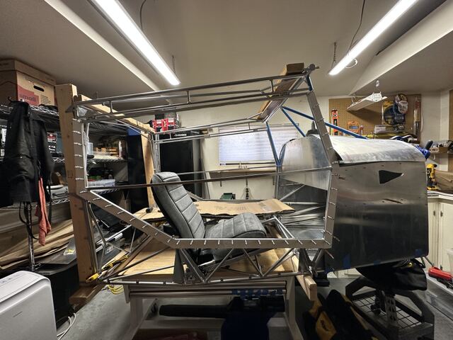
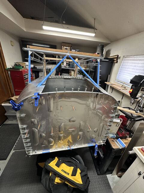
  • Photograph from Looked over the kit before buying it
  • Photograph from Looked over the kit before buying it
  • Photograph from Looked over the kit before buying it
  • Photograph from Looked over the kit before buying it
  • Photograph from Looked over the kit before buying it

Keep a log of your own build

An entry in a minute from a phone in the hangar: the date, the task, the photographs. Sections with how far along each is. The whole log taken out on any day, and kept with the aircraft after it flies. The Builders Log is part of the Hangar Flying membership, $99 a year, with the Panel Designer, MRO and the Marketplace.