
On the RV-4, RV-6, RV-7 and RV-8, the forward spar of the horizontal stabilizer is bolted to the fuselage through an attach angle on the stabilizer and an angle on the fuselage that rests on the upper longerons. The plans give the position of those bolts. Van's Aircraft says some airplanes have been built with the holes significantly displaced from that position, and that it has been answering builders' questions about them one at a time. Service Bulletin SB-00134 sets out the limits for where the bolts may be.
Which airplanes, and by when
The bulletin applies to the RV-4, RV-6 and RV-6A, RV-7 and RV-7A, and RV-8 and RV-8A. It took effect on August 22, 2026, and asks for the inspection within the next 10 flying hours or 90 days from that date, whichever comes first. Ninety days from August 22 is November 20, 2026.
It has been revised four times since it was first released on August 13. Revision 2.2, dated September 18, adds the edge distances in inches as well as ratios, two new figures and a note on bolt size, and Van's posted a revised compliance flowchart with it. An owner who printed an earlier revision should work from the current one.
The bulletin assumes the AN3 bolts called for in the kit instructions. It does not apply to other bolt sizes, and Van's asks owners with a different bolt or a custom attach method to contact it. Some early RV-4s were built with a single bolt on each side; Van's says those should be brought up to the two-bolt attachment shown on the later issues of the drawing.
What gets measured
The work starts with the empennage fairing off. The bolt heads can be seen from above, and the underside of the joint with a mirror and a light. If the bolts look to be outside the bulletin's limits, Van's says to remove the front stabilizer bolts so the holes can be measured properly.
The measurements are the spacing between the two bolts on each side; the edge distance from each bolt hole to the forward edge of the stabilizer's attach angle and of the fuselage angle beneath it; the edge distance from the outboard bolt to the outboard end of each angle; and the distance from the center of each side's bolt pattern to the airplane's centerline. The last two figures are plotted on a chart in the bulletin that marks an acceptable area, an area that is acceptable with recurring inspection, and an unacceptable one.
Edge distance is given as e/D: the distance from the center of a hole to the edge of the part, divided by the hole's diameter. For the AN3 bolt the bulletin uses a 0.190-inch hole.
Van's notes that the joint, and the airframe as a whole, is fairly tolerant of where the outboard bolt falls in the longeron, even where the hole is close to the edge or cuts through the inner edge of the longeron flange, or misses the longeron altogether.
What the results lead to
There are four outcomes, depending on the measurements:
- Within limits: a logbook entry recording compliance.
- Short of the preferred limits but within the bulletin's wider ones: acceptable, provided the relief notch in the stabilizer attach angle and the inside radius of the angle are carefully inspected at every annual or 100-hour inspection, whichever comes first. That recurring inspection goes in the logbook too.
- Some small outboard edge distances in the fuselage angle: a washer plate of 0.125-inch 6061-T6 or 2024-T3 aluminum, capturing both bolts, as the bulletin describes.
- Beyond the bulletin's limits, or an outboard fuselage angle that does not rest on the longeron: contact Van's Aircraft for guidance.
The bulletin also gives limits for the relief notch cut in the stabilizer's attach angle, which some builders cut deeper than the kit instructions show.
Where to read it
The bulletin, its memo and the compliance flowchart are Van's documents and are not reproduced here. They are on Van's service information page, with the change log. An owner should work from the bulletin itself, at its current revision, with its figures in hand. Van's asks anyone who has sold an affected airplane to pass the bulletin to the new owner and tell Van's of the transfer.
Sources
- Van's Aircraft, SB-00134 (Rev 2.2), Horizontal Stabilizer Forward Attach Bolt Position, posted September 18, 2026, and the bulletin itself (13 pages). Both read October 23, 2026.
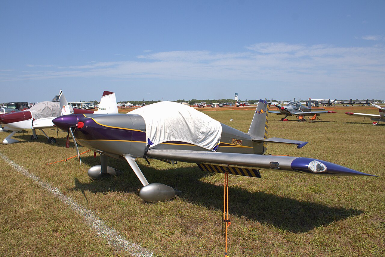
- Photo: Van's RV-7 (N13PD, cn 70343) at Sun 'n Fun 2024_(4-10-2024).jpg) by ZLEA, Wikimedia Commons, CC BY-SA 4.0.