
A terminal is where a wire meets a stud, and the FAA's Advisory Circular 43.13-1B says electrical equipment malfunction "has frequently been traced to poor terminal connections at terminal boards." Chapter 11, section 14 of the circular covers the terminal, the stud it goes on, and the tool that joins it to the wire. The circular is not a regulation, and an aircraft or kit manufacturer's instructions come first where they exist.
What the joint has to do
Paragraph 11-174 sets two requirements for the joint between a wire and its terminal. Its tensile strength should be at least equal to that of the wire itself, and its resistance should be negligible compared with the wire's.
The same paragraph lists what to consider in choosing a terminal: its current rating, the wire size and the diameter of the insulation, whether the conductor and insulation materials are compatible with it, the stud size, and the environment it will work in. It states a preference: "Pre-insulated crimp-type ring-tongue terminals are preferred." Copper terminal lugs should be the solderless crimp style and conform to MIL-T-7928.
The crimp tool
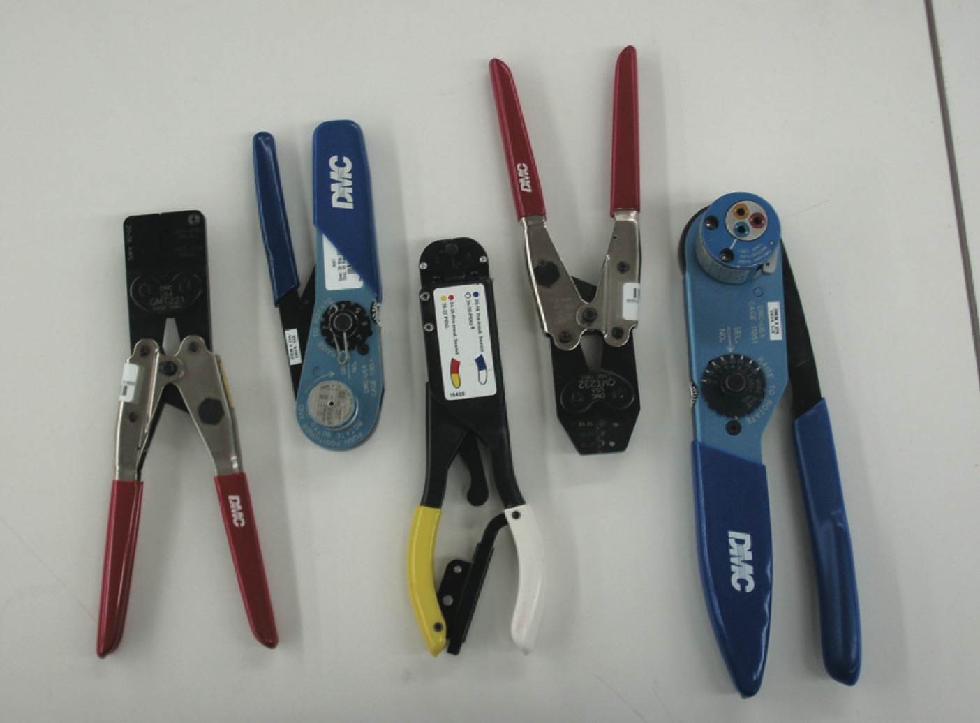
Paragraph 11-178 says crimp-on terminal lugs and splices "must be installed using a high quality ratchet-type, crimping tool," and recommends a calibrated one. The reason it gives is crimp depth, which has to suit each wire size. A crimp that is too deep or not deep enough "may break or cut individual strands, or it may not be tight enough to retain the wire in the terminal." A crimp that is not tight enough is also open to high resistance from corrosion building up between the terminal and the wire.
The tool crimps the barrel to the conductor and, in the same stroke, forms the insulation support onto the wire's insulation.
The circular gives four points for inspecting the tool:
- The full-cycle ratchet must not be able to be released before or during the crimp.
- A tool that does not function, or in which faults are found, is rejected and sent for repair.
- Calibration and adjustment are made only by the manufacturer or an approved calibration laboratory.
- Go/No Go gages are to be used before any crimping, and during the work where possible, to check the crimp's dimensions.
On the stud
Paragraph 11-174 limits what goes on one stud:
- No more than four terminal lugs, or three terminal lugs and a bus bar. A bus bar joining adjacent studs counts toward the total.
- The lug's stud hole should match the diameter of the stud. Where lugs on one stud differ, the largest goes on the bottom and the smallest on top.
- Spacers or washers should not be used between the tongues of terminal lugs.
- Tightening should not deform the lugs or the stud.
- Lugs should be positioned so that none has to be bent to remove the screw or nut, and so that movement of the lugs tends to tighten the connection.
Paragraph 11-176 adds that the lug or wire should be supported next to the stud, unless some other positive locking is provided, so that a side pull on the wire cannot loosen the connection. It says torque values for these connections are normally found in the manufacturer's maintenance instruction manual.
Terminal strips
The circular asks for a terminal strip fitted with barriers, so that terminals on adjacent studs cannot touch, and for studs anchored against rotation. When more than four terminals are to be joined, a small metal bus should be mounted across two or more adjacent studs. In every case the current should be carried by the terminals' contact surfaces and not by the stud.
A strip should be mounted so that loose metal objects cannot fall across its terminals or studs. The circular calls it good practice to provide at least one spare stud, for a later circuit or a broken stud.
Locking the nut
Paragraph 11-179 covers terminals on equipment. Where a locknut is used, it should be the all-metal type. A spring lock washer may be installed under the nut for contact pressure, with a plain washer between the spring washer and the terminal to prevent galling. A plain nut with a spring lock washer and a plain washer may also be used.
Aluminum wire
Aluminum terminal lugs should be crimped to aluminum wire only. The circular asks for special attention to aluminum wire installations, because improperly installed terminals and washers, improper torque and inadequate contact area can lead to excessive voltage drop and high resistance at the junction, and in time to its failure.
Sources
- Photo: FAA, Aviation Maintenance Technician Handbook: Airframe (FAA-H-8083-31B), volume 1, figure 9-156. A work of the U.S. Government.
- FAA, AC 43.13-1B with Change 1, chapter 11, section 14: paragraphs 11-174 to 11-179. Read October 11, 2026.