
Every sheet-metal airplane is held together by rivets, and every builder and mechanic drilling a hole in one has to decide what goes in it and how close to the edge it may sit. The FAA's Advisory Circular 43.13-1B covers that in paragraph 4-57 of chapter 4, a few pages that cover rivet identification, edge distance and spacing, and blind rivets.
The circular is guidance, not a regulation. It gives methods acceptable to the FAA for inspecting and repairing civil aircraft when there are no manufacturer repair or maintenance instructions. On a kit, the kit maker's drawings and construction manual decide what rivet goes where and how far apart. Paragraph 4-57 is the background behind those drawings, and the reference most mechanics use for a repair the manufacturer does not cover.
Reading a rivet
A solid rivet's part number spells out what it is. The circular's example is MS20470AD3-5: MS20470 is the universal head, AD is 2117-T aluminum alloy, 3 is the diameter in thirty-seconds of an inch (3/32), and 5 is the length in sixteenths (5/16). Length is measured from the underside of a universal head, or from the top of a countersunk head. Half sizes are ordered with ".5" after the length, as in MS20470AD4-3.5.
Two head styles cover most work. The MS20426 countersunk rivet, with a 100-degree head, is the standard in the United States where a smooth surface is wanted. The MS20470 universal head replaced the AN470 and may stand in for the older roundhead, flathead and brazier head rivets.
The marking on the head gives the alloy. Table 4-8 of the circular lists them, with each alloy's shear strength:
- A, 1100 aluminum: plain head, 10,000 psi.
- AD, 2117-T: a dimple, 30,000 psi.
- D, 2017-T: a raised dot, 34,000 psi (38,000 psi for 2017-T-HD).
- DD, 2024-T: two raised dashes, 41,000 psi.
- B, 5056: a raised cross, 27,000 psi.
The 2117 rivet is driven as received. The 2017 rivets over 3/16 inch and all 2024 rivets have to be kept in dry ice or refrigerated in the quenched condition until they are driven, or heat treated again just before, because otherwise they are too hard to drive well.
Replacing a rivet
The rule is the same size and strength wherever possible. If the hole is enlarged or damaged, it is drilled or reamed for the next size up, as long as the edge distance and spacing still meet the minimums. A rivet of lower strength is not substituted unless a larger size or more rivets make up the difference. The circular allows one common exception for general repairs: 2117 rivets may replace 2017 rivets of 3/16 inch or less and 2024 rivets of 5/32 inch or less, if the replacements are 1/32 inch larger in diameter.
Edge distance and spacing
Edge distance is measured from the center of the hole to the nearest edge of the sheet. Spacing is measured from the center of one hole to the center of the next. Unless there is reason to think the original structure was deficient, the circular says a repair copies the original spacing and edge distance.
Where the original is suspect, it gives minimums:
- A single row: edge distance at least two rivet diameters, spacing at least three.
- A double row (figure 4-5): two diameters to the edge, four between rows and four between rivets in a row. The figure notes the sheet through the rivet line keeps 75 percent of its strength.
- Three or more rows: two diameters to the edge, three between rows, six between rivets in a row with the rows staggered. The sheet keeps 83 percent of its strength.
The same figure suggests a rivet diameter of about three times the thickness of the thicker sheet.
The driven head
Figure 4-6 gives the shape a properly driven rivet should have. Before driving, the shank stands out about one and a half diameters, never less than one. The formed shop head should be at least one and a half diameters across and about 0.65 diameter high, with half a diameter the least. The figure also draws the faults to look for: a rivet driven at a slant, a head flattened on one side by a bucking bar held crooked, sheets that bulge because they did not fit, sheets driven apart by over-driving, a plate damaged by the riveting tool, and a head cracked because the rivet was too hard.
Blind rivets
Blind rivets go in where only one side can be reached. The circular says their locking is usually not as good as a driven rivet's, so they are not used where a driven rivet can be. It lists where they shall not be used:
- in fluid-tight areas;
- in air intake areas where parts of a rivet could be drawn into the engine;
- on control surfaces, hinges, hinge brackets and flight control actuating systems;
- on wing attachment fittings and landing gear fittings;
- on floats and amphibian hulls below the water line;
- in other heavily stressed places.
For metal repairs to the airframe, the circular's caution says blind rivets must be specifically authorized by the airframe manufacturer or approved by a representative of the FAA. Where a kit is designed around blind rivets, the kit maker's drawings decide where they go.
It also explains why there are two kinds. In a friction-lock rivet, the stem is held only by friction, and vibration can shake it out, which greatly reduces the rivet's shear strength. The circular says a loose one stands out in the standard "smoking rivet" pattern when inspected by eye. Mechanical-lock rivets were developed to stop that: a feature on the head or the puller locks the stem in place.
Sources
- FAA, AC 43.13-1B with Change 1, paragraph 1 (purpose) and chapter 4, section 4, paragraph 4-57, with figures 4-4 to 4-7 and table 4-8. Read October 26, 2026.
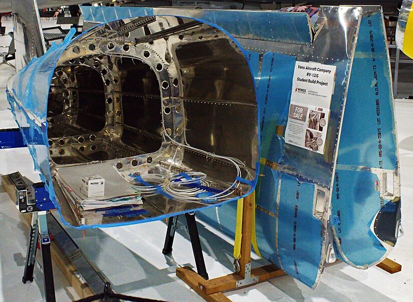
- Picture: Van's RV-12iS (unfinished) (6-17-2025)_(6-17-2025).jpg), ZLEA, 17 June 2025. CC BY-SA 4.0; cropped by Hangar Debrief.