
A wire that is too small for its circuit can fail in two ways. It can run hot, or it can deliver too little voltage to the equipment at the far end. The FAA's Advisory Circular 43.13-1B, Acceptable Methods, Techniques, and Practices: Aircraft Inspection and Repair, covers both in chapter 11, section 5, and gives a method for choosing a size that avoids them. Hangar Flying's wire size calculator works the sum for a single circuit; how its rule compares with the circular's is set out at the end.
The circular is not a regulation. Its first paragraph says it contains methods acceptable to the FAA for the inspection and repair of nonpressurized areas of civil aircraft, "only when there are no manufacturer repair or maintenance instructions." Where an aircraft or kit manufacturer gives wiring instructions, those come first.
The four requirements
Paragraph 11-66 says wires must be sized so that they:
- have sufficient mechanical strength for service conditions;
- do not exceed allowable voltage drop levels;
- are protected by the system's circuit protection devices; and
- meet the circuit's current carrying requirements.
Mechanical strength
The circular gives wire smaller than size 20 special attention. As a general practice, such wires should have additional clamps, be grouped with at least three other wires, and have additional support where they terminate. They should not be used where they will see excessive vibration, repeated bending, or frequent disconnection from screw terminals. Wire with fewer than 19 strands must not be used.
Voltage drop
Table 11-6 gives the maximum acceptable voltage drop in a load circuit, measured between the bus and the equipment's ground:
- 14-volt system: 0.5 volt in continuous operation, 1 volt in intermittent operation.
- 28-volt system: 1 volt in continuous operation, 2 volts in intermittent operation.
The circular treats intermittent operation as lasting two minutes at most. The main power wires, from the generator or battery to the bus, have a separate limit: 2 percent of the regulated voltage.
The limit on a 14-volt system is half that on a 28-volt system. On a long run, the voltage limit can call for a larger wire than the current alone would.
The return path counts. The circular's own example measures the run "including the ground wire." It describes the resistance of a return through the aircraft's structure as generally negligible, but only where adequate bonding to the structure, or a special return path, has been provided. Where the return is a wire, that wire is part of the length.
The FAA's worked example
Paragraph 11-68 works one example on the conductor chart, figure 11-2: a run of 50 feet including the ground wire, a load of 20 amps, a 28-volt source, continuous operation, and a conductor temperature of 20 °C or less. The answer falls between size 8 and size 10 on the chart, and the circular selects the larger wire, size 8, as "the smallest size wire that can be used without exceeding the voltage drop limit."
Figure 11-2 is for continuous current and figure 11-3 for intermittent current.
Current, bundles and altitude
The second test is heat: paragraph 11-68 says the size should be sufficient to prevent overheating of the wire carrying the required current. Figure 11-4a gives the figures for a single copper wire in free air. Paragraph 11-67 presents derating factors for a wire bundled into a harness and for altitude, and paragraph 11-69 works through the calculation.
Paragraph 11-67 adds a limit that is easy to miss: a wire may be able to carry more current than the contacts of its connector. In that case, the contact rating sets the maximum current.
Circuit protection
Paragraph 11-48 states the rule for a breaker's rating: it "must be rated so that it will open before the current rating of the wire attached to it is exceeded, or before the cumulative rating of all loads connected to it are exceeded, whichever is lowest." Paragraph 11-51 states what the breaker is for: it is "designed as circuit protection for the wire," not for the equipment. The same paragraph does not recommend using a circuit breaker as a switch, because doing so shortens the breaker's life.
Table 11-3 is the circular's guide to matching a breaker or fuse to a copper wire:
- Size 22: 5-amp circuit breaker or 5-amp fuse.
- Size 20: 7.5-amp circuit breaker or 5-amp fuse.
- Size 18: 10-amp circuit breaker or 10-amp fuse.
- Size 16: 15-amp circuit breaker or 10-amp fuse.
- Size 14: 20-amp circuit breaker or 15-amp fuse.
- Size 12: 30-amp circuit breaker or 20-amp fuse.
- Size 10: 40-amp circuit breaker or 30-amp fuse.
The table assumes bundles of 15 or more wires in an ambient temperature of 135 °F at altitudes up to 30,000 feet. The circular calls it "conservative for all ordinary aircraft electrical installations" and notes that conditions which differ materially may justify a rating above or below the one shown.
Paragraph 11-47 says a breaker or fuse should be located as close as possible to the bus, and that the equipment's manufacturer will normally specify the one to use.
The Hangar Flying wire size calculator
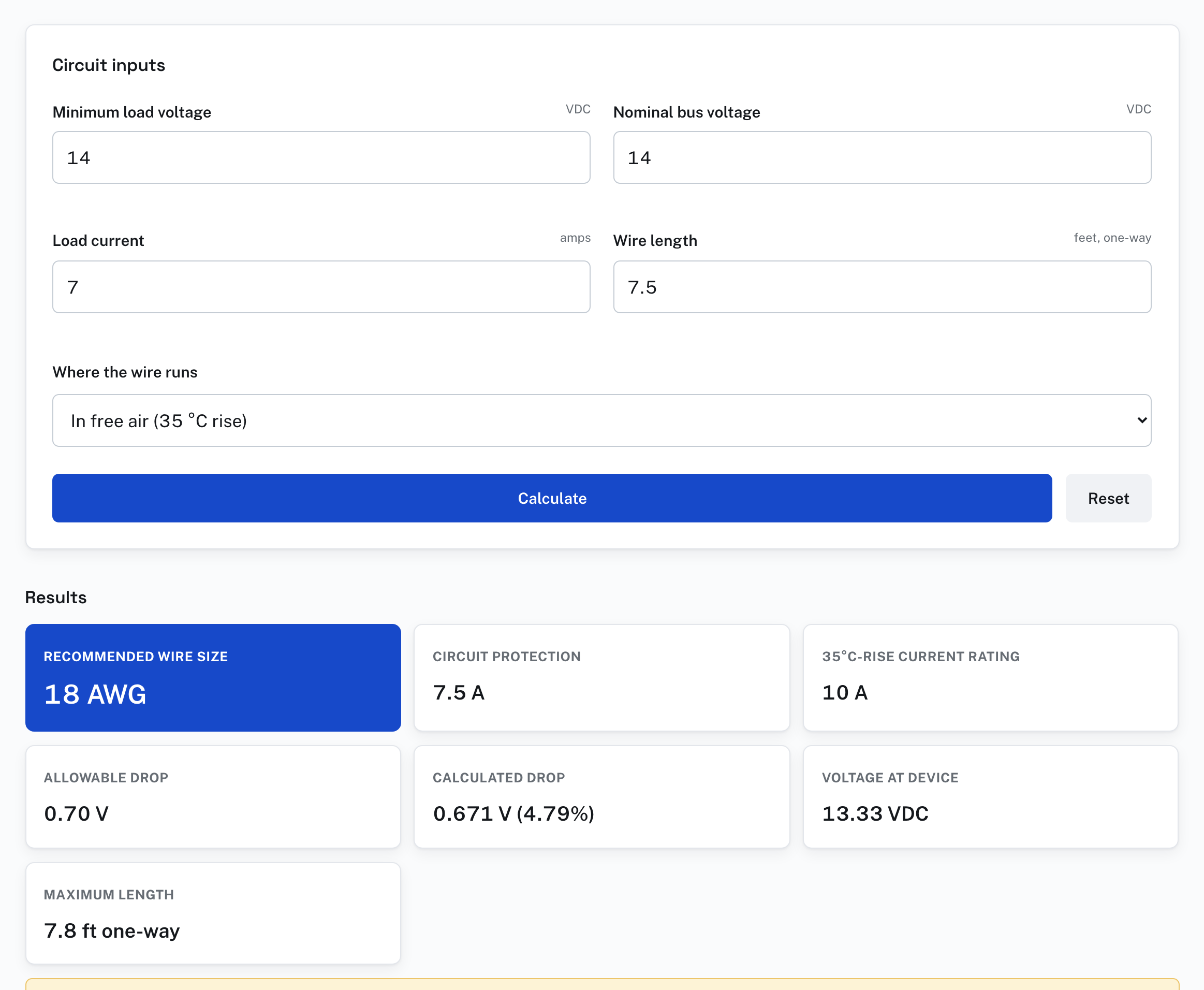
Hangar Flying has a wire size calculator that works this sum for one circuit. It takes the bus voltage, the lowest voltage the load accepts, the current, the one-way length of the run, and whether the wire runs in free air or in a bundle or a hot area. It names the smallest copper wire from size 22 to size 2 that passes both a voltage test and a current test, shows each step of the arithmetic with the circuit's own numbers, and lists the resistance and current figures it uses for every size.
Its voltage rule is not table 11-6. When the load's minimum voltage is entered the same as the bus voltage, the calculator allows a drop of 5 percent: 0.7 volt on a 14-volt system, where the circular allows 0.5 volt in continuous operation. For 7 amps over a run of 7.5 feet with a ground wire of the same length, it answers size 18, with a drop of 0.671 volt.
A builder working to the circular's figure can enter a minimum load voltage 0.5 volt below the bus voltage, 13.5 volts on a 14-volt system. The calculator then holds the drop to 0.5 volt, and for the same circuit it answers size 16.
Its current figures are for a temperature rise of 35 °C in free air or 10 °C in a bundle or a hot area. They are not the figures of the circular's table 11-9, and a wire in a bundle should also be checked against the circular's derating figures.
Sources
- FAA, AC 43.13-1B with Change 1, chapter 11: paragraphs 11-47 to 11-51 and table 11-3 (section 4), paragraphs 11-66 to 11-69, table 11-6 and figures 11-2 and 11-3 (section 5). Read October 11, 2026.