
In a tandem two-seater, a low-wing with a fuel tank close behind the panel, or a high-wing whose structure crowds the back of the panel, depth often decides what fits before the budget does. Manufacturers publish that depth in their installation manuals, though not always the same way: some measure the bare unit, some include the mounting rack and connectors. Hangar Flying's Panel Designer library records each figure with the document it came from. Here they are side by side.
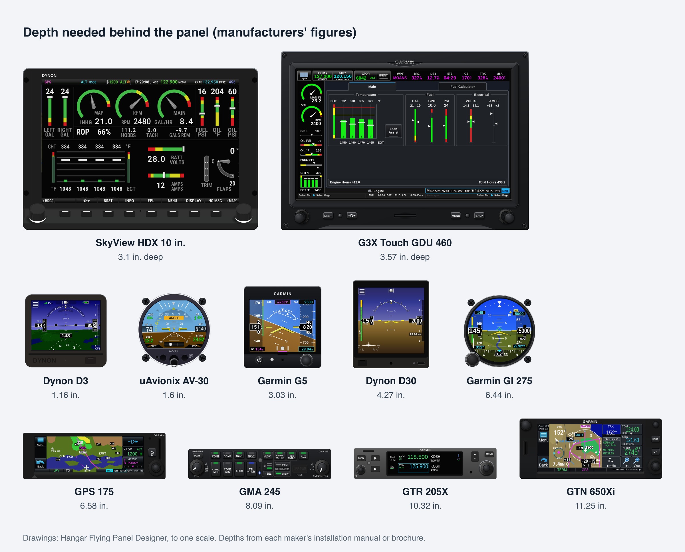
Flight displays: about 3 to 3.6 in.
Dynon gives the SkyView HDX as 3.1 in. deep for the 10-inch, 3.21 in. for the 7-inch and 3.54 in. for the 12-inch. Garmin gives the G3X Touch GDU 460 as 3.57 in. GRT's mounting templates give the Horizon HXr 10.4-inch (2018 and later) as 3.0 in. The big screens are thin. What they need behind them is room for their connectors and for the harness to bend.
Backup instruments: 1.2 to 6.4 in.
This is where the spread is widest. Dynon gives the D3 as 1.16 in. deep and uAvionix gives the AV-30 as 1.6 in. without its connector. Garmin gives the G5 as 3.03 in. and Dynon gives the D30 as 4.27 in. Garmin's GI 275 needs 6.44 in., or 7.40 in. with its connector, more than twice a G5's depth in the same 3-1/8 in. hole.
Navigators, radios and audio panels: 6.6 to 11.25 in.
The stack is where depth runs out. With rack and connectors, Garmin gives:
- GPS 175 IFR navigator: 6.58 in.
- GMA 245 audio panel: 8.09 in.
- GTR 200 com radio: 9.39 in.
- GTR 205 com radio: 10.32 in. (Garmin's installation manual is for the certified GTR 205; the GTR 205X is the experimental model)
- GNX 375 navigator and ADS-B transponder: 10.85 in.
- GNC 355 navigator and com: 11.23 in.
- GTR 225A com radio: 11.23 in.
- GTN 650Xi navigator and NAV/COM: 11.25 in.
Trig gives its TY96 radio as about 9.1 in. in its tray. Its TY91 puts only a small controller in the panel and mounts the radio elsewhere in the airplane, which is one way out when the panel is shallow.
Using the numbers
A published depth is the box. The installation also needs room for the connector backshells, the harness's bend, and a hand to reach the rack screws. Before committing to a layout, it's worth measuring from the back of the panel to the first obstruction at each place a box will go, then checking that figure against the manual's installation drawing rather than a catalog summary.
Sources
- Garmin, G3X/G3X Touch Avionics Installation Manual 190-01115-01 Rev. AZ, Table 2-4 (GDU 460).
- Garmin, G5 Part 23 AML STC Installation Manual 190-01112-10 Rev. 32, Table 1-3; GI 275 Part 23 AML STC Maintenance Manual 190-02246-11 Rev. 11, Table 2-2; GMA 245/245R Installation Manual 190-01879-11 Rev. 14; GTR 200/200B Installation Manual 190-01553-00 Rev. P; GTR 225/GNC 255 TSO Installation Manual 190-01182-02 Rev. F; GTR 205/GNC 215 TSO Installation Manual 190-02766-01 Rev. 6; General Aviation Solutions brochure (GPS 175, GNX 375, GTN 650Xi); Experimental/LSA brochure (GNC 355).
- Dynon, SkyView HDX System Installation Manual Rev P and SkyView System Installation Guide Rev AX; D30 Installation and Maintenance Manual 103997-000 Rev B; D3 Pilot's Guide 103538-000 Rev A.
- GRT Avionics, HXr mounting templates (10.4 in. Version 2).
- uAvionix, AV-30-E Installation Manual, Rev G, Table 6-1.
- Trig Avionics, TY96/TY97 and TY91/TY92 installation manuals, section 3.
- All figures as recorded in Hangar Flying's Panel Designer library from the documents above, read October 18 to 27, 2026.